C8051F005DK Silicon Laboratories Inc, C8051F005DK Datasheet - Page 41
C8051F005DK
Manufacturer Part Number
C8051F005DK
Description
DEV KIT FOR F005/006/007
Manufacturer
Silicon Laboratories Inc
Type
MCUr
Datasheet
1.C8051F005-TB.pdf
(171 pages)
Specifications of C8051F005DK
Contents
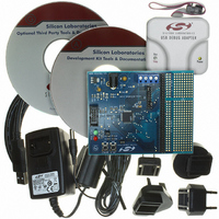
Evaluation Board, Power Supply, USB Cables, Adapter and Documentation
Processor To Be Evaluated
C8051F01x
Interface Type
USB
Silicon Manufacturer
Silicon Labs
Core Architecture
8051
Silicon Core Number
C8051F005
Silicon Family Name
C8051F00x
Lead Free Status / RoHS Status
Contains lead / RoHS non-compliant
For Use With/related Products
Silicon Laboratories C8051 F005/006/007
Lead Free Status / Rohs Status
Lead free / RoHS Compliant
Other names
336-1188
Available stocks
Company
Part Number
Manufacturer
Quantity
Price
Company:

Part Number:
C8051F005DK
Manufacturer:
SiliconL
Quantity:
1


6.2.
The ADC uses VREF to determine its full-scale voltage, thus the reference must be properly configured before
performing a conversion (see Section 9). The ADC has a maximum conversion speed of 100ksps. The ADC
conversion clock is derived from the system clock. Conversion clock speed can be reduced by a factor of 2, 4, 8 or
16 via the ADCSC bits in the ADC0CF Register. This is useful to adjust conversion speed to accommodate
different system clock speeds.
A conversion can be initiated in one of four ways, depending on the programmed states of the ADC Start of
Conversion Mode bits (ADSTM1, ADSTM0) in ADC0CN. Conversions may be initiated by:
Writing a 1 to ADBUSY provides software control of the ADC whereby conversions are performed “on-demand”.
During conversion, the ADBUSY bit is set to 1 and restored to 0 when conversion is complete. The falling edge of
ADBUSY triggers an interrupt (when enabled) and sets the ADCINT interrupt flag. Note: When conversions are
performed “on-demand”, the ADCINT flag, not ADBUSY, should be polled to determine when the
conversion has completed. Converted data is available in the ADC data word MSB and LSB registers, ADC0H,
ADC0L. Converted data can be either left or right justified in the ADC0H:ADC0L register pair (see example in
Figure 6.9) depending on the programmed state of the ADLJST bit in the ADC0CN register.
The ADCTM bit in register ADC0CN controls the ADC track-and-hold mode. In its default state, the ADC input is
continuously tracked, except when a conversion is in progress. Setting ADCTM to 1 allows one of four different
low power track-and-hold modes to be specified by states of the ADSTM1-0 bits (also in ADC0CN):
Modes 1, 2 and 4 (above) are useful when the start of conversion is triggered with a software command or when the
ADC is operated continuously. Mode 3 is used when the start of conversion is triggered by external hardware. In
this case, the track-and-hold is in its low power mode at times when the CNVSTR input is high. Tracking can also
be disabled (shutdown) when the entire chip is in low power standby or sleep modes.
41
C8051F000/1/2/5/6/7
C8051F010/1/2/5/6/7
1. Writing a 1 to the ADBUSY bit of ADC0CN;
2. A Timer 3 overflow (i.e. timed continuous conversions);
3. A rising edge detected on the external ADC convert start signal, CNVSTR;
4. A Timer 2 overflow (i.e. timed continuous conversions).
1. Tracking begins with a write of 1 to ADBUSY and lasts for 3 SAR clocks;
2. Tracking starts with an overflow of Timer 3 and lasts for 3 SAR clocks;
3. Tracking is active only when the CNVSTR input is low;
4. Tracking starts with an overflow of Timer 2 and lasts for 3 SAR clocks.
ADC Modes of Operation
Figure 6.2. 10-Bit ADC Track and Conversion Example Timing
Timer2, Timer3 Overflow;
(ADSTM[1:0]=00, 01, 11)
Write 1 to ADBUSY
(ADSTM[1:0]=10)
SAR Clocks
SAR Clocks
SAR Clocks
ADCTM=1
ADCTM=0
ADCTM=1
ADCTM=0
CNVSTR
A. ADC Timing for External Trigger Source
B. ADC Timing for Internal Trigger Sources
Track or Convert
Low Power or
Low Power or
Convert
Convert
Track Or Convert
1
1
Track
2
2
Track
3
3
4
4
1
5
5
2
6
6
Rev. 1.7
3
7
7
Convert
4
8
8
5
9
9
10 11 12 13 14 15 16 17 18 19
10 11 12 13 14 15 16
6
Convert
7
Convert
Convert
8
9
10 11 12 13 14 15 16
Low Power Mode
Track
Low Power Mode
Track
Related parts for C8051F005DK
Image
Part Number
Description
Manufacturer
Datasheet
Request
R

Part Number:
Description:
SMD/C°/SINGLE-ENDED OUTPUT SILICON OSCILLATOR
Manufacturer:
Silicon Laboratories Inc
Part Number:
Description:
Manufacturer:
Silicon Laboratories Inc
Datasheet:
Part Number:
Description:
N/A N/A/SI4010 AES KEYFOB DEMO WITH LCD RX
Manufacturer:
Silicon Laboratories Inc
Datasheet:
Part Number:
Description:
N/A N/A/SI4010 SIMPLIFIED KEY FOB DEMO WITH LED RX
Manufacturer:
Silicon Laboratories Inc
Datasheet:
Part Number:
Description:
N/A/-40 TO 85 OC/EZLINK MODULE; F930/4432 HIGH BAND (REV E/B1)
Manufacturer:
Silicon Laboratories Inc
Part Number:
Description:
EZLink Module; F930/4432 Low Band (rev e/B1)
Manufacturer:
Silicon Laboratories Inc
Part Number:
Description:
I°/4460 10 DBM RADIO TEST CARD 434 MHZ
Manufacturer:
Silicon Laboratories Inc
Part Number:
Description:
I°/4461 14 DBM RADIO TEST CARD 868 MHZ
Manufacturer:
Silicon Laboratories Inc
Part Number:
Description:
I°/4463 20 DBM RFSWITCH RADIO TEST CARD 460 MHZ
Manufacturer:
Silicon Laboratories Inc
Part Number:
Description:
I°/4463 20 DBM RADIO TEST CARD 868 MHZ
Manufacturer:
Silicon Laboratories Inc
Part Number:
Description:
I°/4463 27 DBM RADIO TEST CARD 868 MHZ
Manufacturer:
Silicon Laboratories Inc
Part Number:
Description:
I°/4463 SKYWORKS 30 DBM RADIO TEST CARD 915 MHZ
Manufacturer:
Silicon Laboratories Inc
Part Number:
Description:
N/A N/A/-40 TO 85 OC/4463 RFMD 30 DBM RADIO TEST CARD 915 MHZ
Manufacturer:
Silicon Laboratories Inc
Part Number:
Description:
I°/4463 20 DBM RADIO TEST CARD 169 MHZ
Manufacturer:
Silicon Laboratories Inc