C8051F020DK Silicon Laboratories Inc, C8051F020DK Datasheet - Page 225
C8051F020DK
Manufacturer Part Number
C8051F020DK
Description
DEV KIT FOR F020/F021/F022/F023
Manufacturer
Silicon Laboratories Inc
Type
MCUr
Datasheet
1.C8051F020DK.pdf
(272 pages)
Specifications of C8051F020DK
Contents
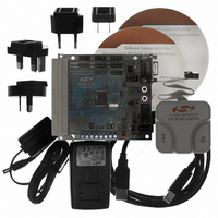
Evaluation Board, Power Supply, USB Cables, Adapter and Documentation
Processor To Be Evaluated
C8051F02x
Interface Type
USB
Silicon Manufacturer
Silicon Labs
Core Architecture
8051
Silicon Core Number
C8051F020
Silicon Family Name
C8051F02x
Lead Free Status / RoHS Status
Contains lead / RoHS non-compliant
For Use With/related Products
Silicon Laboratories C8051 F020/021/022/023
Lead Free Status / Rohs Status
Lead free / RoHS Compliant
Other names
336-1200
Available stocks
Company
Part Number
Manufacturer
Quantity
Price
Company:

Part Number:
C8051F020DK
Manufacturer:
SiliconL
Quantity:
10


22.
The C8051F020/1/2/3 devices contain 5 counter/timers: three are 16-bit counter/timers compatible with those found
in the standard 8051, and two are 16-bit auto-reload timers for use with the ADCs, SMBus, UART1, or for general
purpose use. These can be used to measure time intervals, count external events and generate periodic interrupt
requests. Timer 0 and Timer 1 are nearly identical and have four primary modes of operation. Timer 2 offers addi-
tional capabilities not available in Timers 0 and 1. Timer 3 is similar to Timer 2, but without the capture or Baud Rate
Generator modes. Timer 4 is identical to Timer 2, and can supply baud-rate generation capabilities to UART1.
When functioning as a timer, the counter/timer registers are incremented on each clock tick. Clock ticks are derived
from the system clock divided by either one or twelve as specified by the Timer Clock Select bits (T4M-T0M) in
CKCON, shown in Figure 22.1. The twelve-clocks-per-tick option provides compatibility with the older generation
of the 8051 family. Applications that require a faster timer can use the one-clock-per-tick option.
When functioning as a counter, a counter/timer register is incremented on each high-to-low transition at the selected
input pin. Events with a frequency of up to one-fourth the system clock's frequency can be counted. The input signal
need not be periodic, but it should be held at a given level for at least two full system clock cycles to ensure the level
is sampled.
Timer 0 and Timer 1:
Two 8-bit counter/timers
8-bit counter/timer with
13-bit counter/timer
16-bit counter/timer
(Timer 0 only)
TIMERS
auto-reload
Timer 2:
16-bit counter/timer with
16-bit counter/timer with
Baud rate generator for
auto-reload
UART0
capture
Rev. 1.4
Timer 3:
16-bit timer with auto-
reload
C8051F020/1/2/3
Timer 4
16-bit counter/timer with
16-bit counter/timer with
Baud rate generator for
auto-reload
UART1
capture
225
Related parts for C8051F020DK
Image
Part Number
Description
Manufacturer
Datasheet
Request
R

Part Number:
Description:
SMD/C°/SINGLE-ENDED OUTPUT SILICON OSCILLATOR
Manufacturer:
Silicon Laboratories Inc
Part Number:
Description:
Manufacturer:
Silicon Laboratories Inc
Datasheet:
Part Number:
Description:
N/A N/A/SI4010 AES KEYFOB DEMO WITH LCD RX
Manufacturer:
Silicon Laboratories Inc
Datasheet:
Part Number:
Description:
N/A N/A/SI4010 SIMPLIFIED KEY FOB DEMO WITH LED RX
Manufacturer:
Silicon Laboratories Inc
Datasheet:
Part Number:
Description:
N/A/-40 TO 85 OC/EZLINK MODULE; F930/4432 HIGH BAND (REV E/B1)
Manufacturer:
Silicon Laboratories Inc
Part Number:
Description:
EZLink Module; F930/4432 Low Band (rev e/B1)
Manufacturer:
Silicon Laboratories Inc
Part Number:
Description:
I°/4460 10 DBM RADIO TEST CARD 434 MHZ
Manufacturer:
Silicon Laboratories Inc
Part Number:
Description:
I°/4461 14 DBM RADIO TEST CARD 868 MHZ
Manufacturer:
Silicon Laboratories Inc
Part Number:
Description:
I°/4463 20 DBM RFSWITCH RADIO TEST CARD 460 MHZ
Manufacturer:
Silicon Laboratories Inc
Part Number:
Description:
I°/4463 20 DBM RADIO TEST CARD 868 MHZ
Manufacturer:
Silicon Laboratories Inc
Part Number:
Description:
I°/4463 27 DBM RADIO TEST CARD 868 MHZ
Manufacturer:
Silicon Laboratories Inc
Part Number:
Description:
I°/4463 SKYWORKS 30 DBM RADIO TEST CARD 915 MHZ
Manufacturer:
Silicon Laboratories Inc
Part Number:
Description:
N/A N/A/-40 TO 85 OC/4463 RFMD 30 DBM RADIO TEST CARD 915 MHZ
Manufacturer:
Silicon Laboratories Inc
Part Number:
Description:
I°/4463 20 DBM RADIO TEST CARD 169 MHZ
Manufacturer:
Silicon Laboratories Inc