R0K561622S000BE Renesas Electronics America, R0K561622S000BE Datasheet - Page 682
R0K561622S000BE
Manufacturer Part Number
R0K561622S000BE
Description
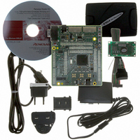
KIT STARTER FOR H8SX/1622
Manufacturer
Renesas Electronics America
Series
Renesas Starter Kits (RSK)r
Type
MCUr
Specifications of R0K561622S000BE
Contents
Board, Cables, CD, Debugger, Power Supply
Silicon Manufacturer
Renesas
Features
Coding And Debugging, E10A Emulator, RS232 Serial Connection
Kit Contents
Board
Silicon Family Name
H8SX/1622F
Silicon Core Number
R5F61622N50LGV
Lead Free Status / RoHS Status
Lead free / RoHS Compliant
For Use With/related Products
H8SX/1622
Lead Free Status / RoHS Status
Lead free / RoHS Compliant, Lead free / RoHS Compliant


Section 16 Serial Communication Interface (SCI)
Rev. 2.00 Sep. 16, 2009 Page 652 of 1036
REJ09B0414-0200
Figure 16.13 Sample Multiprocessor Serial Reception Flowchart (1)
No
No
No
Read ORER and FER flags in SSR
Read ORER and FER flags in SSR
Read receive data in RDR
Read receive data in RDR
Set MPIE bit in SCR to 1
Read RDRF flag in SSR
Read RDRF flag in SSR
Clear RE bit in SCR to 0
All data received?
FER ∨ ORER = 1
This station’s ID?
FER ∨ ORER = 1
Start reception
Initialization
RDRF = 1
RDRF = 1
<End>
Yes
Yes
Yes
Yes
No
No
Yes
No
Error processing
Yes
(Continued on
[3]
[1]
[2]
next page)
[4]
[5]
[1] SCI initialization:
[2] ID reception cycle:
[3] SCI state check, ID reception and
[4] SCI state check and data reception:
[5] Receive error processing and break
The RxD pin is automatically designated
as the receive data input pin.
Set the MPIE bit in SCR to 1.
comparison:
Read SSR and check that the RDRF
flag is set to 1, then read the receive
data in RDR and compare it with this
station’s ID. If the data is not this
station’s ID, set the MPIE bit to 1 again,
and clear the RDRF flag to 0. If the data
is this station’s ID, clear the RDRF flag
to 0.
Read SSR and check that the RDRF
flag is set to 1, then read the data in
RDR.
detection:
If a receive error occurs, read the ORER
and FER flags in SSR to identify the
error. After performing the appropriate
error processing, ensure that the ORER
and FER flags are both cleared to 0.
Reception cannot be resumed if either
of these flags is set to 1. In the case of a
framing error, a break can be detected
by reading the RxD pin value.
Related parts for R0K561622S000BE
Image
Part Number
Description
Manufacturer
Datasheet
Request
R

Part Number:
Description:
KIT STARTER FOR M16C/29
Manufacturer:
Renesas Electronics America
Datasheet:

Part Number:
Description:
KIT STARTER FOR R8C/2D
Manufacturer:
Renesas Electronics America
Datasheet:

Part Number:
Description:
R0K33062P STARTER KIT
Manufacturer:
Renesas Electronics America
Datasheet:

Part Number:
Description:
KIT STARTER FOR R8C/23 E8A
Manufacturer:
Renesas Electronics America
Datasheet:

Part Number:
Description:
KIT STARTER FOR R8C/25
Manufacturer:
Renesas Electronics America
Datasheet:

Part Number:
Description:
KIT STARTER H8S2456 SHARPE DSPLY
Manufacturer:
Renesas Electronics America
Datasheet:

Part Number:
Description:
KIT STARTER FOR R8C38C
Manufacturer:
Renesas Electronics America
Datasheet:

Part Number:
Description:
KIT STARTER FOR R8C35C
Manufacturer:
Renesas Electronics America
Datasheet:

Part Number:
Description:
KIT STARTER FOR R8CL3AC+LCD APPS
Manufacturer:
Renesas Electronics America
Datasheet:
Part Number:
Description:
KIT STARTER FOR RX610
Manufacturer:
Renesas Electronics America
Datasheet:

Part Number:
Description:
KIT STARTER FOR R32C/118
Manufacturer:
Renesas Electronics America
Datasheet:

Part Number:
Description:
KIT DEV RSK-R8C/26-29
Manufacturer:
Renesas Electronics America
Datasheet:

Part Number:
Description:
KIT STARTER FOR SH7124
Manufacturer:
Renesas Electronics America
Datasheet:

Part Number:
Description:
KIT DEV FOR SH7203
Manufacturer:
Renesas Electronics America
Datasheet:
Part Number:
Description:
KIT STARTER FOR R8C/18191A1B
Manufacturer:
Renesas Electronics America
Datasheet: