R0K561622S000BE Renesas Electronics America, R0K561622S000BE Datasheet - Page 756
R0K561622S000BE
Manufacturer Part Number
R0K561622S000BE
Description
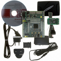
KIT STARTER FOR H8SX/1622
Manufacturer
Renesas Electronics America
Series
Renesas Starter Kits (RSK)r
Type
MCUr
Specifications of R0K561622S000BE
Contents
Board, Cables, CD, Debugger, Power Supply
Silicon Manufacturer
Renesas
Features
Coding And Debugging, E10A Emulator, RS232 Serial Connection
Kit Contents
Board
Silicon Family Name
H8SX/1622F
Silicon Core Number
R5F61622N50LGV
Lead Free Status / RoHS Status
Lead free / RoHS Compliant
For Use With/related Products
H8SX/1622
Lead Free Status / RoHS Status
Lead free / RoHS Compliant, Lead free / RoHS Compliant


Section 18 A/D Converter
(2)
1. Set the ADSTCLR bit in ADCR to 1.
2. When the ADST bit in ADCSR is set to 1 by software, TPU, TMR, or an external trigger
3. When A/D conversion for each channel is completed, the A/D conversion result is sequentially
4. When A/D conversion of all selected channels is completed, the ADF bit in ADCSR is set to 1.
Rev. 2.00 Sep. 16, 2009 Page 726 of 1036
REJ09B0414-0200
ADST
ADF
Channel 0 (AN0)
operation state
Channel 1 (AN1)
operation state
Channel 2 (AN2)
operation state
Channel 3 (AN3)
operation state
ADDRA
ADDRB
ADDRC
ADDRD
input, A/D conversion starts on the first channel in the specified channel group. Consecutive
A/D conversion on a maximum of four channels (SCANE and SCANS = B'10) or on a
maximum of eight channels (SCANE and SCANS = B'11) can be selected. When consecutive
A/D conversion is performed on four channels, A/D conversion starts on AN0 when CH3 and
CH2 = B'00, whereas starts on AN4 when CH3 and CH2 = B'01. When consecutive A/D
conversion is performed on eight channels, A/D conversion starts on AN0 when CH3 = B'0.
transferred to the corresponding ADDR of each channel.
If the ADIE bit is set to 1 at this time, an ADI interrupt request is generated.
One-Cycle Scan Mode
Notes: 1.
2.
(Continuous Scan Mode, Three Channels (AN0 to AN2) Selected)
↓ indicates the timing of instruction execution by software.
Data being converted is ignored.
Waiting for
conversion
Waiting for conversion
Waiting for conversion
Waiting for conversion
Figure 18.3 Example of A/D Conversion
Set *
A/D
conver-
sion 1
1
Transfer
A/D conversion consecutive execution
A/D
conver-
sion 2
Waiting for conversion
A/D conversion result 1
A/D
conver-
sion 3
Waiting for conversion
A/D conversion time
A/D
conver-
sion 4
A/D conversion result 2
A/D conversion result 3
A/D
conver-
sion 5
A/D conversion result 4
Waiting for conversion
Waiting for conversion
*
Clear *
2
Waiting for
conversion
1
Clear *
1
Related parts for R0K561622S000BE
Image
Part Number
Description
Manufacturer
Datasheet
Request
R

Part Number:
Description:
KIT STARTER FOR M16C/29
Manufacturer:
Renesas Electronics America
Datasheet:

Part Number:
Description:
KIT STARTER FOR R8C/2D
Manufacturer:
Renesas Electronics America
Datasheet:

Part Number:
Description:
R0K33062P STARTER KIT
Manufacturer:
Renesas Electronics America
Datasheet:

Part Number:
Description:
KIT STARTER FOR R8C/23 E8A
Manufacturer:
Renesas Electronics America
Datasheet:

Part Number:
Description:
KIT STARTER FOR R8C/25
Manufacturer:
Renesas Electronics America
Datasheet:

Part Number:
Description:
KIT STARTER H8S2456 SHARPE DSPLY
Manufacturer:
Renesas Electronics America
Datasheet:

Part Number:
Description:
KIT STARTER FOR R8C38C
Manufacturer:
Renesas Electronics America
Datasheet:

Part Number:
Description:
KIT STARTER FOR R8C35C
Manufacturer:
Renesas Electronics America
Datasheet:

Part Number:
Description:
KIT STARTER FOR R8CL3AC+LCD APPS
Manufacturer:
Renesas Electronics America
Datasheet:
Part Number:
Description:
KIT STARTER FOR RX610
Manufacturer:
Renesas Electronics America
Datasheet:

Part Number:
Description:
KIT STARTER FOR R32C/118
Manufacturer:
Renesas Electronics America
Datasheet:

Part Number:
Description:
KIT DEV RSK-R8C/26-29
Manufacturer:
Renesas Electronics America
Datasheet:

Part Number:
Description:
KIT STARTER FOR SH7124
Manufacturer:
Renesas Electronics America
Datasheet:

Part Number:
Description:
KIT DEV FOR SH7203
Manufacturer:
Renesas Electronics America
Datasheet:
Part Number:
Description:
KIT STARTER FOR R8C/18191A1B
Manufacturer:
Renesas Electronics America
Datasheet: