AT91SAM7A1-EK Atmel, AT91SAM7A1-EK Datasheet - Page 12
AT91SAM7A1-EK
Manufacturer Part Number
AT91SAM7A1-EK
Description
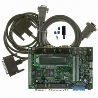
BOARD EVAL FOR AT91SAM7A1
Manufacturer
Atmel
Series
AT91SAM Smart ARMr
Type
MCUr
Datasheet
1.AT91SAM7A1-EK.pdf
(31 pages)
Specifications of AT91SAM7A1-EK
Contents
Evaluation Board, Parallel Cable and CD-ROM
Processor To Be Evaluated
AT91SAM7A1
Data Bus Width
32 bit
Interface Type
RS-232
For Use With/related Products
AT91SAM7A1
Lead Free Status / RoHS Status
Contains lead / RoHS non-compliant
Available stocks
Company
Part Number
Manufacturer
Quantity
Price
Company:

Part Number:
AT91SAM7A1-EK
Manufacturer:
Atmel
Quantity:
2


6114A–ATARM–09/04
3.4
3.5
3-2
Application
Interface
CAN Bus
The board provides the following application interfaces:
Table 3-1. Board Application Interfaces
For more details, refer to Figure 4-3 and Figure 4-4.
The CAN0 module is connected to a female SubD9 connector (J7) via the CAN driver
MN2.The pinout is described in Table 3-2.
Figure 3-1. Female DB9 Connector
Part
Reset push button
Red LED DS2
Orange LED DS3
Green LED DS4
SW2 push button
SW3 push button
SW4 push button
Buzzer
LCD connected to PIO
5
9
4
8
AT91SAM7A1-EK Evaluation Board User Guide
3
7
Detects and then resets the board when the
3.3V supply voltage drops below 2.7V. Allows
manual reset of both board and
microcontroller.
Connected to timer (or I/O) pin TIOA0 (GPT
module)
Connected to timer (or I/O) pin TIOA1 (GPT
module)
Connected to timer (or I/O) pin TIOB0 (GPT
module)
Connected to input pins TIOA2 and TIOB1 (or
I/O) of the timer (GPT module)
Connected to GIC (Generic Interrupt
Controller) module IRQ0 input. Allows the
user to generate interrupts manually.
Connected to the PWM0 output. It
demonstrates the PWM (Pulse Width
Modulation) features. It is possible to
enable/disable the buzzer by opening/closing
jumper J10. The PWM0 output signal can be
a 3V3 or 5V (jumper J3). The voltage
influences the volume of the sound.
Displays 2 lines of 16 characters each. The
LCD is driven by the PIO which can be
powered by 3V3 or 5V. The LCD tolerates
these two voltages. Users can display
messages on the LCD. The contrast voltage is
provided by the PWM1 and can be measured
by ADC0 channel 0.
2
6
1
Description
Related parts for AT91SAM7A1-EK
Image
Part Number
Description
Manufacturer
Datasheet
Request
R

Part Number:
Description:
MCU ARM9 64K SRAM 144-LFBGA
Manufacturer:
Atmel
Datasheet:

Part Number:
Description:
IC ARM7 MCU FLASH 256K 100LQFP
Manufacturer:
Atmel
Datasheet:

Part Number:
Description:
IC ARM9 MPU 217-LFBGA
Manufacturer:
Atmel
Datasheet:
Part Number:
Description:
MCU ARM9 ULTRA LOW PWR 217-LFBGA
Manufacturer:
Atmel
Datasheet:

Part Number:
Description:
MCU ARM9 324-TFBGA
Manufacturer:
Atmel
Datasheet:
Part Number:
Description:
IC MCU ARM9 SAMPLING 217CBGA
Manufacturer:
Atmel
Datasheet:
Part Number:
Description:
IC ARM9 MCU 217-LFBGA
Manufacturer:
Atmel
Datasheet:

Part Number:
Description:
IC ARM9 MCU 208-PQFP
Manufacturer:
Atmel
Datasheet:
Part Number:
Description:
MCU ARM 512K HS FLASH 100-LQFP
Manufacturer:
Atmel
Datasheet:

Part Number:
Description:
MCU ARM 512K HS FLASH 100-TFBGA
Manufacturer:
Atmel
Datasheet:
Part Number:
Description:
IC ARM9 MCU 200 MHZ 324-TFBGA
Manufacturer:
Atmel
Datasheet:

Part Number:
Description:
IC ARM MCU 16BIT 128K 256BGA
Manufacturer:
Atmel
Datasheet:

Part Number:
Description:
IC ARM7 MCU 32BIT 128K 64LQFP
Manufacturer:
Atmel
Datasheet:

Part Number:
Description:
IC ARM7 MCU FLASH 256K 128-LQFP
Manufacturer:
Atmel
Datasheet:
Part Number:
Description:
IC ARM7 MCU FLASH 512K 128-LQFP
Manufacturer:
Atmel
Datasheet: