MSC8156ADS Freescale Semiconductor, MSC8156ADS Datasheet - Page 43
MSC8156ADS
Manufacturer Part Number
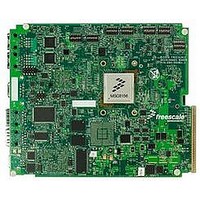
MSC8156ADS
Description
BOARD ADS FOR MSC8156
Manufacturer
Freescale Semiconductor
Type
DSPr
Datasheet
1.MSC8156ADS.pdf
(72 pages)
Specifications of MSC8156ADS
Contents
Board
Leaded Process Compatible
Yes
Rohs Compliant
Yes
Peak Reflow Compatible (260 C)
Yes
For Use With/related Products
MSC8156
Lead Free Status / RoHS Status
Lead free / RoHS Compliant


2.16.6.10 BCSR9 Board Control Miscellaneous Register 1
On the board, the BCSR9 acts as a board control register. The BCSR9, which may be read or written at
any time, receives its defaults upon Power-On-Reset. The BCSR9 fields are described in Table 2-24.
Freescale Semiconductor
BIT
BIT
0
1
2
3
4
5
6
7
5
6
7
RS232EN
FRMEN
SGMIIRST
RGMIIRST1
RGMIIRST2
RGMIIRST
RSTDDRM
RSRV9
MBOOT
MIIDSP
PHYCLK
MNEMONIC
MNEMONIC
UART Port Transceiver Enable. Upon activation (low), the RS-232
Transceiver, using the UART port of the MSC8156, is enabled. When
negated (high), the RS-232 Transceiver enters standby mode.
TDM E1/T1 Framers 1,2 Enable. Upon activation (high), the E1/T1
framers work in normal mode. When low, the E1/T1 Framers stay in
reset and release MSC8156 TDM ports lines for Ethernet
functionality.
Reset to SGMII Switch. Upon activation (low), the switch stays in
reset. When negated (high), SGMII switch works normally. The
SGMII switch configuration EEPROM is programmed at reset of the
device.
Reset to GE1 port RGMII phy. Upon activation (low), the phy stays
in reset. When negated (high), RGMII phy loads configuration and
goes in the working mode.
Reset to GE2 port RGMII phy. Upon activation (low), the phy stays
in reset. When negated (high), RGMII phy loads configuration and
goes in the working mode.
Reset to RGMII Switch. Upon activation (low), the Switch stays in
reset. When negated (high), RGMII Switch and goes in the working
mode.
reset. When high the DDR Modules function normally.
Not Implemented.
Reset to DDR2,3 Modules. When low the DDR modules stay in
I 2 C Master/Slave Boot. A high sets I 2 C Master Boot by asserting
STOP_BS signal. When this bit is low MSC815x stops boot until
STOP_BS input getsa low from Boot Master.
MSC815x MII Bus Select. A low selects the MSC815x MII bus to program
PHYs and the SGMII switch. When this bit is high, the FPGA MII controller
can access the GETH peripherals.This feature is available starting with the
ADS rev Pilot.
PHY2 Clock Enable. When high, the 125 MHz clock is driven to the PHY2
clockin input. This bit allows you to program the PHY2 even when the ADS
is configured in TDM mode. A low disables PHY2.
Table 2-24. BCSR9 Peripheral Control (Offset 9)
MSC8156ADS Reference Manual, Rev. 2.1
Table 2-23. BCSR8 CTRL1 (Offset 8)
Function
Function
‘0’ when nSRST is
‘0’ when nSRST is
‘0’ when nSRST is
‘0’ when nSRST is
Programming Logic (FPGA)
DEF on PRST
otherwise
otherwise
otherwise
otherwise
asserted,
asserted,
asserted,
asserted,
SW2.6 &
‘0’
‘1’
‘1’
DEF on
0
SW2.7
PRST
‘1’
‘0’
—
—
—
—
‘1’
‘1’
‘1’
‘1’
ATT.
R,W
R,W
R,W
ATT.
R,W
R,W
R,W
R,W
R,W
R,W
R,W
-
2-31
Related parts for MSC8156ADS
Image
Part Number
Description
Manufacturer
Datasheet
Request
R

Part Number:
Description:
Six-core Digital Signal Processor
Manufacturer:
Freescale Semiconductor, Inc
Datasheet:
Part Number:
Description:
Manufacturer:
Freescale Semiconductor, Inc
Datasheet:
Part Number:
Description:
Manufacturer:
Freescale Semiconductor, Inc
Datasheet:
Part Number:
Description:
Manufacturer:
Freescale Semiconductor, Inc
Datasheet:
Part Number:
Description:
Manufacturer:
Freescale Semiconductor, Inc
Datasheet:
Part Number:
Description:
Manufacturer:
Freescale Semiconductor, Inc
Datasheet:
Part Number:
Description:
Manufacturer:
Freescale Semiconductor, Inc
Datasheet:
Part Number:
Description:
Manufacturer:
Freescale Semiconductor, Inc
Datasheet:
Part Number:
Description:
Manufacturer:
Freescale Semiconductor, Inc
Datasheet:
Part Number:
Description:
Manufacturer:
Freescale Semiconductor, Inc
Datasheet:
Part Number:
Description:
Manufacturer:
Freescale Semiconductor, Inc
Datasheet:
Part Number:
Description:
Manufacturer:
Freescale Semiconductor, Inc
Datasheet:
Part Number:
Description:
Manufacturer:
Freescale Semiconductor, Inc
Datasheet:
Part Number:
Description:
Manufacturer:
Freescale Semiconductor, Inc
Datasheet:
Part Number:
Description:
Manufacturer:
Freescale Semiconductor, Inc
Datasheet: