ATAVRONEKIT Atmel, ATAVRONEKIT Datasheet - Page 31
ATAVRONEKIT
Manufacturer Part Number
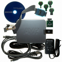
ATAVRONEKIT
Description
KIT AVR/AVR32 DEBUGGER/PROGRMMR
Manufacturer
Atmel
Series
AVR®r
Type
Debuggerr
Specifications of ATAVRONEKIT
Contents
Programmer/Debugger
Processor To Be Evaluated
AVR32
Data Bus Width
32 bit
Interface Type
ISP, JTAG
Core Architecture
AVR
Kit Contents
ATAVRONEKIT
Tool / Board Applications
General Purpose MCU, MPU, DSP, DSC
Development Tool Type
Hardware / Software - Dev Kit (Dev Tool)
Rohs Compliant
Yes
Mcu Supported Families
AVR32 32-bit MCU
For Use With/related Products
AVR® Devices
Lead Free Status / RoHS Status
Lead free / RoHS Compliant
Available stocks
Company
Part Number
Manufacturer
Quantity
Price
Company:

Part Number:
ATAVRONEKIT
Manufacturer:
Atmel
Quantity:
135


15. T/C - 16-bit Timer/Counter
15.1
15.2
8067M–AVR–09/10
Features
Overview
•
•
•
•
•
•
•
•
•
•
•
•
•
XMEGA A1 has eight Timer/Counters, four Timer/Counter 0 and four Timer/Counter 1. The dif-
ference between them is that Timer/Counter 0 has four Compare/Capture channels, while
Timer/Counter 1 has two Compare/Capture channels.
The Timer/Counters (T/C) are 16-bit and can count any clock, event or external input in the
microcontroller. A programmable prescaler is available to get a useful T/C resolution. Updates of
Timer and Compare registers are double buffered to ensure glitch free operation. Single slope
PWM, dual slope PWM and frequency generation waveforms can be generated using the Com-
pare Channels.
Through the Event System, any input pin or event in the microcontroller can be used to trigger
input capture, hence no dedicated pins is required for this. The input capture has a noise cancel-
ler to avoid incorrect capture of the T/C, and can be used to do frequency and pulse width
measurements.
A wide range of interrupt or event sources are available, including T/C Overflow, Compare
match and Capture for each Compare/Capture channel in the T/C.
PORTC, PORTD, PORTE and PORTF each has one Timer/Counter 0 and one Timer/Counter1.
Notation of these Timer/Counters are TCC0 (Time/Counter C0), TCC1, TCD0, TCD1, TCE0,
TCE1, TCF0, and TCF1, respectively.
Eight 16-bit Timer/Counters
Four Compare or Capture (CC) Channels in Timer/Counter 0
Two Compare or Capture (CC) Channels in Timer/Counter 1
Double Buffered Timer Period Setting
Double Buffered Compare or Capture Channels
Waveform Generation:
Input Capture:
Event Counter with Direction Control
Timer Overflow and Timer Error Interrupts and Events
One Compare Match or Capture Interrupt and Event per CC Channel
Supports DMA Operation
Hi-Resolution Extension (Hi-Res)
Advanced Waveform Extension (AWEX)
– Four Timer/Counters of type 0
– Four Timer/Counters of type 1
– Single Slope Pulse Width Modulation
– Dual Slope Pulse Width Modulation
– Frequency Generation
– Input Capture with Noise Cancelling
– Frequency capture
– Pulse width capture
– 32-bit input capture
XMEGA A1
31
Related parts for ATAVRONEKIT
Image
Part Number
Description
Manufacturer
Datasheet
Request
R

Part Number:
Description:
DEV KIT FOR AVR/AVR32
Manufacturer:
Atmel
Datasheet:

Part Number:
Description:
INTERVAL AND WIPE/WASH WIPER CONTROL IC WITH DELAY
Manufacturer:
ATMEL Corporation
Datasheet:
Part Number:
Description:
Low-Voltage Voice-Switched IC for Hands-Free Operation
Manufacturer:
ATMEL Corporation
Datasheet:
Part Number:
Description:
MONOLITHIC INTEGRATED FEATUREPHONE CIRCUIT
Manufacturer:
ATMEL Corporation
Datasheet:
Part Number:
Description:
AM-FM Receiver IC U4255BM-M
Manufacturer:
ATMEL Corporation
Datasheet:
Part Number:
Description:
Monolithic Integrated Feature Phone Circuit
Manufacturer:
ATMEL Corporation
Datasheet:
Part Number:
Description:
Multistandard Video-IF and Quasi Parallel Sound Processing
Manufacturer:
ATMEL Corporation
Datasheet:
Part Number:
Description:
High-performance EE PLD
Manufacturer:
ATMEL Corporation
Datasheet:
Part Number:
Description:
8-bit Flash Microcontroller
Manufacturer:
ATMEL Corporation
Datasheet:
Part Number:
Description:
2-Wire Serial EEPROM
Manufacturer:
ATMEL Corporation
Datasheet: