MA300012 Microchip Technology, MA300012 Datasheet - Page 16
MA300012
Manufacturer Part Number
MA300012
Description
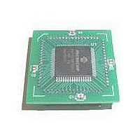
MODULE DSPIC30F SAMPLE 64QFP
Manufacturer
Microchip Technology
Specifications of MA300012
Module/board Type
dsPIC30F Plug-in Module
Lead Free Status / RoHS Status
Lead free / RoHS Compliant
For Use With/related Products
DM240001
Lead Free Status / RoHS Status
Lead free / RoHS Compliant, Lead free / RoHS Compliant


dsPIC30F
5.4
The DSP engine consists of a high-speed, single-cycle,
17-bit x 17-bit multiplier, a barrel shifter and a 40-bit
adder/subtractor with two target accumulators, round
and saturation logic, all of which enable efficient
execution of computationally intensive DSP algorithms.
The 17-bit x 17-bit multiplier is also utilized for MCU-
based multiply instructions.
The DSP engine also has the capability to perform
inherent accumulator-to-accumulator operations, which
require no additional data. These instructions are ADD,
SUB and NEG. This feature greatly simplifies basic
arithmetic operations on 32-bit or 40-bit data.
A block diagram of the DSP engine is shown in
Figure 5-4.
5.4.1
The 17 x 17-bit multiplier is capable of signed or
unsigned operation. It can suitably scale its output to
support either 1.31 fractional (Q31) or 32-bit integer
results, thereby diminishing the need to manually
post-process multiplication results for fractional data.
5.4.2
The data accumulators have a 40-bit adder/subtractor
with automatic sign-extension logic. It can select one of
two accumulators (A or B) as its pre-accumulation
source and post-accumulation destination. For the ADD
and LAC instructions, the data to be accumulated or
loaded can be optionally scaled via the barrel shifter
prior to accumulation.
The adder/subtractor generates overflow Status bits
SA/SB and OA/OB, which are latched and reflected in
the STATUS Register and can also optionally generate
an Arithmetic Error Trap:
• Overflow from bit 39. This is a catastrophic
• Overflow into guard bits 32 through 39. This is a
DS70043F-page 14
overflow in which the sign of the accumulator is
destroyed.
recoverable overflow. This bit (OA/OB) is set
whenever all the guard bits are not identical to
each other.
DSP Engine
17X17-BIT MULTIPLIER
40-BIT ACCUMULATORS
5.4.3
The adder has an additional saturation block that
controls accumulator data saturation, if selected. It
uses the result of the adder, the overflow Status bits
described above, and the user-configured control bits
to determine when to saturate and to what value to
saturate (a 40-bit or a 32-bit value).
In addition to adder/subtractor saturation, writes to data
space can also be saturated, but without affecting the
contents of the source accumulator.
The rounding logic performs a conventional (biased) or
convergent (unbiased) data rounding function during
an accumulator write (store). The Round mode is user-
selectable. Rounding generates a 16-bit, 1.15 data
value, which is passed to the data space write
saturation logic. Data space write saturation ensures
that the data in the accumulator is written back
accurately even when rounding is performed. If
rounding is not indicated by the instruction, a truncated
1.15 data value is stored and the least significant word
(lsb) is simply discarded.
SATURATION AND OVERFLOW
© 2005 Microchip Technology Inc.
Related parts for MA300012
Image
Part Number
Description
Manufacturer
Datasheet
Request
R

Part Number:
Description:
Manufacturer:
Microchip Technology Inc.
Datasheet:
Part Number:
Description:
Manufacturer:
Microchip Technology Inc.
Datasheet:
Part Number:
Description:
Manufacturer:
Microchip Technology Inc.
Datasheet:
Part Number:
Description:
Manufacturer:
Microchip Technology Inc.
Datasheet:
Part Number:
Description:
Manufacturer:
Microchip Technology Inc.
Datasheet:
Part Number:
Description:
Manufacturer:
Microchip Technology Inc.
Datasheet:
Part Number:
Description:
Manufacturer:
Microchip Technology Inc.
Datasheet:
Part Number:
Description:
Manufacturer:
Microchip Technology Inc.
Datasheet: