MA300012 Microchip Technology, MA300012 Datasheet - Page 18
MA300012
Manufacturer Part Number
MA300012
Description
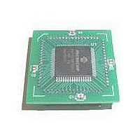
MODULE DSPIC30F SAMPLE 64QFP
Manufacturer
Microchip Technology
Specifications of MA300012
Module/board Type
dsPIC30F Plug-in Module
Lead Free Status / RoHS Status
Lead free / RoHS Compliant
For Use With/related Products
DM240001
Lead Free Status / RoHS Status
Lead free / RoHS Compliant, Lead free / RoHS Compliant


dsPIC30F
6.0
The dsPIC30F has four processor exceptions (traps)
and up to 45 sources of interrupts, which must be
arbitrated based on a priority scheme.
The processor core is responsible for reading the
Interrupt Vector Table (IVT) and transferring the
address contained in the interrupt vector to the
program counter.
The Interrupt Vector Table (IVT) and Alternate Interrupt
Vector Table (AIVT) are placed near the beginning of
program memory (0x000004) for ease of debugging.
The interrupt controller hardware pre-processes the
interrupts before they are presented to the CPU.
The interrupts and traps are enabled, prioritized and
controlled
Registers.
TABLE 6-1:
DS70043F-page 16
Number
Vector
10
12
13
14
15
16
17
18
19
20
21
22
23
24
25
26
27
28
29
30
31
32
33
34
35
11
8
9
EXCEPTION PROCESSING
using
INTERRUPT VECTORS
IVT Address
0x00001A
0x00001C
0x00001E
0x00002A
0x00002C
0x00002E
0x00003A
0x00003C
0x00003E
0x00004A
0x000014
0x000016
0x000018
0x000020
0x000022
0x000024
0x000026
0x000028
0x000030
0x000032
0x000034
0x000038
0x000040
0x000042
0x000044
0x000046
0x000048
0x000036
centralized
Special
AIVT Address
0x00009C
0x0000AA
0x0000AC
0x0000AE
0x0000BA
0x0000BC
0x0000BE
0x0000C0
0x0000C2
0x0000C4
0x0000C6
0x0000C8
0x0000CA
0x00009A
0x00009E
0x0000A0
0x0000A2
0x0000A4
0x0000A6
0x0000A8
0x0000B0
0x0000B2
0x0000B4
0x0000B6
0x0000B8
0x000094
0x000096
0x000098
Function
INT0 – External Interrupt 0
IC1 – Input Compare 1
OC1 – Output Compare 1
T1 – Timer1
IC2 – Input Capture 2
OC2 – Output Compare 2
T2 – Timer2
T3 – Timer3
SPI1
U1RX – UART1 Receiver
U1TX – UART1 Transmitter
ADC – ADC Convert Done
NVM – NVM Write Complete
I2C Slave Operation – Message Detect
I2C Master Operation – Message Event Complete
Change Notice Interrupt
INT1 – External Interrupt 1
IC7 – Input Capture 7
IC8 – Input Capture 8
OC3 – Output Compare 3
OC4 – Output Compare 4
T4 – Timer4
T5 – Timer5
INT2 – External Interrupt 2
U2RX – UART2 Receiver
U2TX – UART2 Transmitter
SPI2
CAN1
Each individual interrupt source has its own vector
address and can be individually enabled and prioritized
in user software. Each interrupt source also has its own
status flag. This independent control and monitoring of
the interrupt eliminates the need to poll various status
flags to determine the interrupt source
Table 6-1 contains information about the interrupt
vector.
Certain interrupts have specialized control bits for
features like edge or level triggered interrupts,
interrupt-on-change, etc. Control of these features
remains
generates the interrupt.
The special DISI instruction can be used to disable
the processing of interrupts of priorities 6 and lower for
a certain number of instruction cycles, during which
the DISI bit remains set.
within
Interrupt Source
the
© 2005 Microchip Technology Inc.
Peripheral
module,
which
Related parts for MA300012
Image
Part Number
Description
Manufacturer
Datasheet
Request
R

Part Number:
Description:
Manufacturer:
Microchip Technology Inc.
Datasheet:
Part Number:
Description:
Manufacturer:
Microchip Technology Inc.
Datasheet:
Part Number:
Description:
Manufacturer:
Microchip Technology Inc.
Datasheet:
Part Number:
Description:
Manufacturer:
Microchip Technology Inc.
Datasheet:
Part Number:
Description:
Manufacturer:
Microchip Technology Inc.
Datasheet:
Part Number:
Description:
Manufacturer:
Microchip Technology Inc.
Datasheet:
Part Number:
Description:
Manufacturer:
Microchip Technology Inc.
Datasheet:
Part Number:
Description:
Manufacturer:
Microchip Technology Inc.
Datasheet: