MA300012 Microchip Technology, MA300012 Datasheet - Page 19
MA300012
Manufacturer Part Number
MA300012
Description
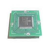
MODULE DSPIC30F SAMPLE 64QFP
Manufacturer
Microchip Technology
Specifications of MA300012
Module/board Type
dsPIC30F Plug-in Module
Lead Free Status / RoHS Status
Lead free / RoHS Compliant
For Use With/related Products
DM240001
Lead Free Status / RoHS Status
Lead free / RoHS Compliant, Lead free / RoHS Compliant


TABLE 6-1:
6.1
Each interrupt source can be user assigned to one of 8
priority levels, 1 through 7. Levels 7 and 1 represent the
highest and lowest maskable priorities, respectively. A
priority level of 0 disables the interrupt.
Since more than one interrupt request source may be
assigned to a user specified priority level, a means is
provided to assign priority within a given level. This
method is called “Natural Order Priority.”
The Natural Order Priority of an interrupt is numerically
identical to its vector number. The natural order priority
scheme has 0 as the highest priority and 53 as the
lowest priority.
The ability for the user to assign every interrupt to one
of eight priority levels implies that the user can assign
a very high overall priority level to an interrupt with a
low natural order priority, thereby providing much
flexibility in designing applications that use a large
number of peripherals.
© 2005 Microchip Technology Inc.
Number
Vector
53-61
36
37
38
39
40
41
42
43
44
45
46
47
48
49
50
51
52
Interrupt Priority
0x00006E-0x00007E 0x00006E-0x00007E Reserved
INTERRUPT VECTORS (CONTINUED)
IVT Address
0x00004C
0x00005C
0x00006C
0x00004E
0x000050
0x000052
0x000054
0x000056
0x000058
0x00005A
0x00005E
0x000060
0x000062
0x000064
0x000066
0x000068
0x00006A
AIVT Address
0x0000CC
0x0000CE
0x0000DA
0x0000DC
0x0000DE
0x0000EC
0x0000D0
0x0000D2
0x0000D4
0x0000D6
0x0000D8
0x0000E0
0x0000E4
0x0000EA
0x0000E2
0x0000E6
0x0000E8
IC3 – Input Capture 3
IC4 – Input Capture 4
IC5 – Input Capture 5
IC6 – Input Capture 6
OC5 – Output Compare 5
OC6 – Output Compare 6
OC7 – Output Compare 7
OC8 – Output Compare 8
INT3 – External Interrupt 3
INT4 – External Interrupt 4
CAN2
PWM – PWM Period Match
QEI – Position Counter Compare
LVD – Low Voltage Detect
FLTA – MCPWM FAULT A
FLTB – MCPWM FAULT B
DCI – Codec Transfer Done
6.2
Interrupts, by default, are nestable. Any ISR that is in
progress may be interrupted by another source of
interrupt with a higher user assigned priority level.
Interrupt nesting may be optionally disabled by setting
the NSTDIS control bit (INTCON1<15>). When the
NSTDIS control bit is set, all interrupts in progress will
force the CPU priority to level 7 by setting IPL<2:0> =
111. This action will effectively mask all other sources
of interrupt until a RETFIE instruction is executed.
When interrupt nesting is disabled, the user assigned
interrupt priority levels will have no effect, except to
resolve conflicts between simultaneous pending
interrupts.
The IPL<2:0> bits become read-only when interrupt
nesting is disabled. This prevents the user software
from setting IPL<2:0> to a lower value, which would
effectively re-enable interrupt nesting.
Interrupt Nesting
Interrupt Source
dsPIC30F
DS70043F-page 17
Related parts for MA300012
Image
Part Number
Description
Manufacturer
Datasheet
Request
R

Part Number:
Description:
Manufacturer:
Microchip Technology Inc.
Datasheet:
Part Number:
Description:
Manufacturer:
Microchip Technology Inc.
Datasheet:
Part Number:
Description:
Manufacturer:
Microchip Technology Inc.
Datasheet:
Part Number:
Description:
Manufacturer:
Microchip Technology Inc.
Datasheet:
Part Number:
Description:
Manufacturer:
Microchip Technology Inc.
Datasheet:
Part Number:
Description:
Manufacturer:
Microchip Technology Inc.
Datasheet:
Part Number:
Description:
Manufacturer:
Microchip Technology Inc.
Datasheet:
Part Number:
Description:
Manufacturer:
Microchip Technology Inc.
Datasheet: