MA300012 Microchip Technology, MA300012 Datasheet - Page 23
MA300012
Manufacturer Part Number
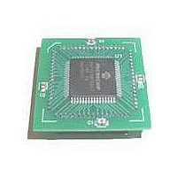
MA300012
Description
MODULE DSPIC30F SAMPLE 64QFP
Manufacturer
Microchip Technology
Specifications of MA300012
Module/board Type
dsPIC30F Plug-in Module
Lead Free Status / RoHS Status
Lead free / RoHS Compliant
For Use With/related Products
DM240001
Lead Free Status / RoHS Status
Lead free / RoHS Compliant, Lead free / RoHS Compliant


7.6
The primary function of the Watchdog Timer (WDT) is
to reset the processor in the event of a software
malfunction. The WDT is a free running timer that runs
off an on-chip RC oscillator, requiring no external
component. The WDT Timer continues to operate even
if the main processor clock (e.g., the crystal oscillator)
fails.
The Watchdog Timer can be “Enabled” or “Disabled”
either through a Configuration bit (FWDTEN) in the
Configuration register or
(SWDTEN).
Any device programmer capable of programming
dsPIC devices (such as Microchip’s PRO MATE
programmer) allows programming of this and other
Configuration bits to the desired state. If enabled, the
WDT increments until it overflows or “times out”. A
WDT time-out forces a device Reset (except during
Sleep).
7.7
The Fail-Safe Clock Monitor (FSCM) allows the device
to continue to operate even in the event of an oscillator
failure. The FSCM function is enabled by programming.
If the FSCM function is enabled, the LPRC internal
oscillator runs at all times (except during Sleep mode)
and is not subject to control by the watchdog timer.
In the event of an oscillator failure, the FSCM
generates a Clock Failure Trap event and switches the
system clock over to the FRC oscillator. The application
program then can either attempt to restart the oscillator,
or execute a controlled shutdown. The Trap can be
treated as a warm Reset by simply loading the Reset
address into the oscillator fail trap vector.
© 2005 Microchip Technology Inc.
Watchdog Timer (WDT)
Fail-Safe Clock Monitor (FSCM)
through an SFR
®
bit
II
7.8
The Reset system combines all Reset sources and
controls the device Master Reset signal.
Device Reset sources include:
• POR: Power-on Reset
• SWR: RESET instruction
• EXTR: MCLR Reset
• WDTR: Watchdog Timer Time-out Reset
• BOR: Brown-out Reset
• TRAPR: Trap Conflict Reset
• IOPUWR: Attempted execution of an Illegal
Opcode, or Indirect Addressing using an
Uninitialized W Register
Reset System
dsPIC30F
DS70043F-page 21
Related parts for MA300012
Image
Part Number
Description
Manufacturer
Datasheet
Request
R

Part Number:
Description:
Manufacturer:
Microchip Technology Inc.
Datasheet:
Part Number:
Description:
Manufacturer:
Microchip Technology Inc.
Datasheet:
Part Number:
Description:
Manufacturer:
Microchip Technology Inc.
Datasheet:
Part Number:
Description:
Manufacturer:
Microchip Technology Inc.
Datasheet:
Part Number:
Description:
Manufacturer:
Microchip Technology Inc.
Datasheet:
Part Number:
Description:
Manufacturer:
Microchip Technology Inc.
Datasheet:
Part Number:
Description:
Manufacturer:
Microchip Technology Inc.
Datasheet:
Part Number:
Description:
Manufacturer:
Microchip Technology Inc.
Datasheet: