MA300012 Microchip Technology, MA300012 Datasheet - Page 34
MA300012
Manufacturer Part Number
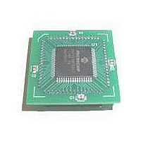
MA300012
Description
MODULE DSPIC30F SAMPLE 64QFP
Manufacturer
Microchip Technology
Specifications of MA300012
Module/board Type
dsPIC30F Plug-in Module
Lead Free Status / RoHS Status
Lead free / RoHS Compliant
For Use With/related Products
DM240001
Lead Free Status / RoHS Status
Lead free / RoHS Compliant, Lead free / RoHS Compliant


dsPIC30F
9.9
The UART is a full-duplex asynchronous system that
can communicate with peripheral devices, such as
personal computers, RS-232, and RS-485 interfaces.
The dsPIC30F devices have one or more UART’s.
The key features of the UART module are:
• Full-duplex operation with 8- or 9-bit data
• Even, Odd or No Parity options (for 8-bit data)
• One or two Stop bits
• Fully integrated Baud Rate Generator with 16-bit
• Baud rates range from up to 2.5 Mbps and down
• 4-character deep transmit data buffer
• 4-character deep receive data buffer
• Parity, Framing and Buffer Overrun error detection
• 16x Baud Clock output for IrDA
• Support for interrupt on Address Detect
• Separate Transmit and Receive interrupts:
• Loopback mode for diagnostics
• Alternate TX/RX pins on smaller pin count
9.10
The I
useful for communicating with other peripheral or
microcontroller devices. These peripheral devices may
be Serial EEPROMs, shift registers, display drivers,
A/D converters, etc.
The Inter-Integrated Circuit (I
hardware support for both Slave and Multi-Master
operations.
The key features of the I
• I
• I
• I
• Serial clock synchronization for I
• I
• Slew Rate Control for 100 kHz and 400 kHz bus
In I
module will override the data direction bits for these
pins.
DS70043F-page 32
prescaler
to 38 Hz at 30 MIPs
(9th bit = 1)
- On transmission of 1 or 4 characters
- On reception of 1, 3 and 4 characters
devices, for efficient pin utilization.
address.
master and slaves.
used as a handshake mechanism to suspend and
resume serial transfer (serial clock stretching).
collision and will arbitrate accordingly.
speeds.
2
2
2
2
2
C Slave operation supports 7- and 10-bit address.
C Master operation supports 7- and 10-bit
C port allows bidirectional transfers between
C supports Multi-Master operation. Detects bus
C mode, pin SCL is clock and pin SDA is data. The
2
C module is a synchronous serial interface,
UART Module
I
2
C
TM
Module
2
C module are:
2
C) module offers full
®
2
support
C port can be
9.11
The Controller Area Network (CAN) module is a serial
interface useful for communicating with other CAN
modules or microcontroller devices. This interface/
protocol was designed to allow communications within
noisy environments.
The CAN module is a communication controller
implementing the CAN 2.0 A/B protocol, as defined in
the BOSCH specification. The module supports CAN
1.2, CAN 2.0A, CAN2.0B Passive and CAN 2.0B Active
versions of the protocol. Details of these protocols can
be found in the BOSCH CAN specification.
The CAN module features:
• Implementation of the CAN protocol CAN 1.2,
• Standard and extended data frames
• Data lengths of 0-8 bytes
• Programmable bit rate up to 1 Mbit/sec
• Support for remote frames
• Double buffered receiver with two prioritized
• Six full (standard/extended identifier) acceptance
• Two full acceptance filter masks, one each
• Three transmit buffers with application specified
• Programmable wake-up functionality with
• Programmable Loopback mode supports self-test
• Signaling via interrupt capabilities for all CAN
• Programmable clock source
• Programmable link to Timer module for time-
• Low-power Sleep and Idle mode
The CAN Bus module consists of a protocol engine and
message buffering/control. The CAN protocol engine
handles all functions for receiving and transmitting
messages on the CAN bus. Messages are transmitted
by first loading the appropriate data registers. Status
and errors can be checked by reading the appropriate
registers. Any message detected on the CAN bus is
checked for errors and then matched against filters to
see if it should be received and stored in one of the
receive registers.
CAN 2.0A and CAN 2.0B
received message storage buffers (each buffer
may contain up to 8 bytes of data)
filters, two associated with the high priority
receive buffer, and four associated with the low
priority receive buffer
associated with the high and low priority receive
buffers
prioritization and abort capability (each buffer may
contain up to 8 bytes of data)
integrated low pass filter
operation
receiver and transmitter error states
stamping and network synchronization
Controller Area Network (CAN)
Module
© 2005 Microchip Technology Inc.
Related parts for MA300012
Image
Part Number
Description
Manufacturer
Datasheet
Request
R

Part Number:
Description:
Manufacturer:
Microchip Technology Inc.
Datasheet:
Part Number:
Description:
Manufacturer:
Microchip Technology Inc.
Datasheet:
Part Number:
Description:
Manufacturer:
Microchip Technology Inc.
Datasheet:
Part Number:
Description:
Manufacturer:
Microchip Technology Inc.
Datasheet:
Part Number:
Description:
Manufacturer:
Microchip Technology Inc.
Datasheet:
Part Number:
Description:
Manufacturer:
Microchip Technology Inc.
Datasheet:
Part Number:
Description:
Manufacturer:
Microchip Technology Inc.
Datasheet:
Part Number:
Description:
Manufacturer:
Microchip Technology Inc.
Datasheet: