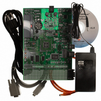
DM300004-2 Microchip Technology, DM300004-2 Datasheet
DM300004-2
Specifications of DM300004-2


Related parts for DM300004-2

DM300004-2 Summary of contents
Page 1
... Connectivity Development Board 2004 Microchip Technology Inc. dsPICDEM.net and dsPICDEM.net User’s Guide ™ 1 ™ 2 DS51471A ...
Page 2
... PICLAB, PICtail, PowerCal, PowerInfo, PowerMate, PowerTool, rfLAB, rfPICDEM, Select Mode, Smart Serial, SmartTel and Total Endurance are trademarks of Microchip Technology Incorporated in the U.S.A. and other countries. SQTP is a service mark of Microchip Technology Incorporated in the U.S.A. All other trademarks mentioned herein are property of their respective companies. ...
Page 3
... Chapter 4. HTTP Web Server Demonstration 4.1 Introduction ................................................................................................... 49 4.2 Highlights ...................................................................................................... 49 4.3 Demonstration Overview .............................................................................. 49 4.4 Demonstration Setup .................................................................................... 50 4.5 Configuring your Laptop or Desktop PC ....................................................... 51 4.6 HTTP Web Server Demonstration ............................................................... 52 2004 Microchip Technology Inc. dsPICDEM.net™ 1 AND dsPICDEM.net 2 CONNECTIVITY DEVELOPMENT BOARD Table of Contents USER’S GUIDE DS51471A-page iii ...
Page 4
... Troubleshooting the Connection .................................................................. 81 6.9 Regulatory Compliance Reference Information ........................................... 84 6.10 ITU-T Specifications ................................................................................... 86 Chapter 7. dsPICDEM.net Development Hardware 7.1 dsPICDEM.net Hardware Components ........................................................ 87 Appendix A. Hardware Schematics A.1 Board Layout and Schematics ..................................................................... 93 Index ...........................................................................................................................107 Worldwide Sales and Service ...................................................................................109 DS51471A-page iv 2004 Microchip Technology Inc. ...
Page 5
... Chapter 7: dsPICDEM.net™ Development Hardware – This chapter describes the hardware included on the of the dsPICDEM.net 1 and dsPICDEM.net 2 boards. • Appendix A: Hardware Schematics – This Appendix contains hardware layout and schematic diagrams of the dsPICDEM.net 1 and dsPICDEM.net 2. 2004 Microchip Technology Inc. dsPICDEM.net™ 1 AND dsPICDEM.net 2 CONNECTIVITY DEVELOPMENT BOARD Preface ® ...
Page 6
... The revision level of the document. Examples #define START c:\autoexec.bat <label>, <exp> pic30-as [main.s] errorlevel {0|1} " " filename list " [ list_option..., " " list_option ] 0xFFFF, 0x007A char isascii (char, ch); File > Save OK, Cancel <Tab>, <Ctrl-C> MPLAB IDE User’s Guide 2004 Microchip Technology Inc. ...
Page 7
... This document is a supplement to the dsPIC30F Family Reference Manual. ® MPLAB ASM30, MPLAB This document helps you use Microchip Technology’s language tools for dsPIC devices based on GNU technology. The language tools discussed are: • MPLAB ASM30 Assembler • MPLAB LINK30 Linker • MPLAB LIB30 Archiver/Librarian • ...
Page 8
... Links to other useful web sites related to Microchip products Engineer’s Toolbox • Design Tips • Device Errata Other Available Information • Latest Microchip Press Releases • Listing of Seminars and Events • Job Postings DS51471A-page 4 ® ® Navigator or Microsoft Internet Explorer. The Microchip 2004 Microchip Technology Inc. ...
Page 9
... MPLAB IDE, MPLAB SIM and MPLAB SIM30 simulators, MPLAB IDE Project Manager and general editing and debugging features. Programmers – The latest information on Microchip device programmers. These include the PRO MATE programmer. 2004 Microchip Technology Inc. ® II device programmer and PICSTART Preface ® ...
Page 10
... Microchip's development systems software products. Plus, this line provides information on how customers can receive any currently available upgrade kits. The Hotline Numbers are: 1-800-755-2345 for U.S. and most of Canada. 1-480-792-7302 for the rest of the world. DS51471A-page 6 2004 Microchip Technology Inc. ...
Page 11
... Note: For the sample applications described in this manual, connect to an analog line only. You could damage the modem if you use a non-analog line (e.g., digital or PBX multiline). 2004 Microchip Technology Inc. dsPICDEM.net™ 1 AND dsPICDEM.net 2 CONNECTIVITY DEVELOPMENT BOARD USER’S GUIDE ...
Page 12
... Serial Communication Channels • Single RS-232 communication channel • 6-pin terminal block and configuration jumper for RS-485 and RS-422 communication on UART1 from the dsPIC device • Single CAN communication channel DS51471A-page 8 and AV with direct input from 9V, AC/ 2004 Microchip Technology Inc. ...
Page 13
... Device Clocking • 7.3728 MHz crystal, X3, for dsPIC device • Socket U16, clock oscillator for dsPIC device (alternate clock source, X3 removed) • Pad for 32.768 kHz crystal (XTAL2) and load caps 2004 Microchip Technology Inc. dsPICDEM.net DEVELOPMENT BOARD Introduction DS51471A-page 9 ...
Page 14
... V.22bis Soft Modem Demonstration – The dsPIC30F6014 plug-in device is pre-programmed with an ITU-T compliant V.22bis/V.22 modem demonstration that lets you to connect and transfer data between the dsPIC30F Soft Modem and an ITU-T compliant reference modem. This demonstration is described fully in Chapter 6. “V.22bis Soft Modem Demonstration”. DS51471A-page 10 2004 Microchip Technology Inc. ...
Page 15
... MPLAB ICD 2 In-Circuit Debugger Quick Start Guide (DS51268) • MPLAB ICE Emulator User’s Guide (DS51159) You can obtain these reference documents from your nearest Microchip sales office (listed in the back of this document downloading them from the Microchip web site (www.microchip.com). 2004 Microchip Technology Inc. Introduction DS51471A-page 11 ...
Page 16
... PICDEM.net™ 1 and dsPICDEM.net 2 Connectivity Dev Board User’s Guide NOTES: DS51471A-page 12 2004 Microchip Technology Inc. ...
Page 17
... Before starting, copy the Tutorial files from the dsPICDEM.net Sample Applications folder on the dsPICDEM.net Development Kit Software CD to your c:\ drive (see Figure 2-1). 2004 Microchip Technology Inc. dsPICDEM.net™ 1 AND dsPICDEM.net 2 CONNECTIVITY DEVELOPMENT BOARD Chapter 2. Tutorial USER’S GUIDE ...
Page 18
... FIGURE 2-2: Select dsPIC30F6014 5. Select dsPIC30F6014 as the device and click Next>. The Project Wizard Step Two dialog displays (see Figure 2-3). DS51471A-page 14 TUTORIAL CODE FILES PROJECT WIZARD, STEP 1, SELECT A DEVICE Copy Tutorial folder from CD to your C:\ drive 2004 Microchip Technology Inc. ...
Page 19
... From Toolsuite Contents, select MPLAB LINK30 Object Linker (pic30-Id.exe the Location block, click Browse... and navigate to: C:\pic30_tools\Bin\pic30-ld.exe. 8. Click Next> to continue. The Project Wizard Step Three dialog displays (see Figure 2-4). 2004 Microchip Technology Inc. PROJECT WIZARD, STEP 2, SELECT LANGUAGE TOOLSUITE Tutorial DS51471A-page 15 ...
Page 20
... Note: The linker script file and header file locations for your environment may be different. The location will depend on where you installed the C30 compiler. DS51471A-page 16 PROJECT WIZARD, STEP 3, NAME YOUR PROJECT 2004 Microchip Technology Inc. ...
Page 21
... C:\Tutorial 5. Click Finish. After the project wizard completes, the MPLAB project window shows the project and all the added files (see Figure 2-7). 2004 Microchip Technology Inc. PROJECT WIZARD, STEP 4, ADD FILES TO PROJECT PROJECT WIZARD SUMMARY SCREEN Tutorial DS51471A-page 17 ...
Page 22
... At this point a project and workspace have been created in MPLAB. MyTutorial.mcw is the workspace file and MyTutorial.mcp is the project file. Double-click the dsPICDEMnet Tutorial.c file in the project window to open it. MPLAB should look similar to Figure 2-8. FIGURE 2-8: DS51471A-page 18 PROJECT WINDOW MPLAB WORKSPACE 2004 Microchip Technology Inc. ...
Page 23
... The tutorial project does not explicitly use any libraries, but the C compiler startup library code is always automatically linked into the project. Use the Project>Build Options>Project menu to specify the location of the library files as shown in Figure 2-10. 2004 Microchip Technology Inc. CODE BUILDING PROCESS LCD display.c STAGE ONE ...
Page 24
... Add a Library Path by browsing to: C:\pic30_tools\lib Note: The library path for your environment may be different. The location will depend on where you installed the C30 compiler. 3. Select the MPLAB LINK30 tab to display the linker settings (see Figure 2-11). DS51471A-page 20 BUILD OPTIONS 2004 Microchip Technology Inc. ...
Page 25
... From the Project menu select Make. The Build Output window displays (see Figure 2-12). 2. Observe the progress of the build. 3. When the BUILD SUCCEEDED message displays you are ready to program the device. 2004 Microchip Technology Inc. MPLAB LINK30 BUILD OPTIONS Tutorial DS51471A-page 21 ...
Page 26
... Figure 2-13). Accept the settings resulting from your build. However, make sure these device categories are set up as shown here: Category Oscillator Source Primary Oscillator Mode Watchdog Timer Comm Channel Select DS51471A-page 22 BUILD OUTPUT Setting Primary Oscillator XT w/PLL 4x Disabled Use PGC/EMUC and PGD/EMUD 2004 Microchip Technology Inc. ...
Page 27
... Connect the MPLAB ICD 2 to modular connector labeled ICD on the dsPICDEM.net board with the provided short RJ-11cable. 3. Apply power to the board. FIGURE 2-14: PC running MPLAB USB Port 2004 Microchip Technology Inc. CONFIGURATION SETTINGS TUTORIAL DEMONSTRATION SETUP ® IDE ® Connect MPLAB ...
Page 28
... From the Debugger menu, select Settings to display the ICD Debugger settings (see Figure 2-16). FIGURE 2-16: Make sure this option is selected: Allow MPLAB ICD 2 to select memories and ranges DS51471A-page 24 ENABLING MPLAB ICD 2 MPLAB ICD 2 DEBUGGER SETTINGS 2004 Microchip Technology Inc. ...
Page 29
... Figure 2-17. The part is now programmed and is ready to run. FIGURE 2-17: 9. Run the code (Debugger>Run). The MPLAB Output window should indicate that the target is running (see Figure 2-18). 2004 Microchip Technology Inc. MPLAB ICD 2 PROGRAM READY Tutorial DS51471A-page 25 ...
Page 30
... Note: When debugging with MPLAB ICD always necessary to reprogram the part with the new code after each build. MPLAB will remind you with a message that states “Program memory has changed since last operation.” DS51471A-page 26 TUTORIAL PROGRAM RUNNING Project status bar shows program running 2004 Microchip Technology Inc. ...
Page 31
... Press <F6> to reset the program. The green arrow moves to address 00000, the goto _reset instruction, as shown in Figure 2-20. The linker inserted this instruction to make the program branch to the start of the code. FIGURE 2-20: 2004 Microchip Technology Inc. Halt Reset Single Step ...
Page 32
... FIGURE 2-22: Right-click TMR1 = 0 and select Run to Cursor The code runs briefly until it reaches the specified line. It then halts with the green arrow pointing to the next line, as shown in Figure 2-23. DS51471A-page 28 PROGRAM SINGLE STEPPED RUN TO CURSOR COMMAND 2004 Microchip Technology Inc. ...
Page 33
... Note: An alternate method is to simply double click the line. This feature may need to be enabled by using the Edit>Properties menu. For this example, find the following line of code and set a breakpoint. IFS0bits.T1IF = 0; 2004 Microchip Technology Inc. PROGRAM HALTED AT CURSOR LOCATION /512; in the code window. CY ...
Page 34
... To familiarize yourself with several dsPIC peripherals and associated board functions proceed to Chapter 3. “Quick Start Program”. The quick start sample project in Chapter 3 provides several code module building blocks to help you accelerate your proficiency with the dsPICDEM.net board. DS51471A-page 30 SETTING BREAKPOINT 2004 Microchip Technology Inc. ...
Page 35
... MPLAB C30 compiler to form a simple quick start project. As you work with the step-by-step instructions you will become increasingly familiar with key features of the dsPIC30F. 2004 Microchip Technology Inc. dsPICDEM.net™ 1 AND dsPICDEM.net 2 CONNECTIVITY DEVELOPMENT BOARD USER’S GUIDE ...
Page 36
... The folder should contain these files: h files: • defines.h • delay.h • lcd.h inc files • device_Fcy.inc • Si3021_mode.inc • Si3021_outputs.inc DS51471A-page 32 DEMONSTRATION CODE FILES • nic_init_param.h • nic_strings.h • strings.h Copy Quick Start folder from CD to your C:\ drive 2004 Microchip Technology Inc. ...
Page 37
... One dialog (see Figure 3-2). FIGURE 3-2: Select dsPIC30F6014 5. Select dsPIC30F6014 as the device and click Next>. The Project Wizard Step Two dialog displays (see Figure 3-3). 2004 Microchip Technology Inc. Quick Start Program • init_Sram.c • init_Timers.s • init_Uart.s • isr_Adc.s • ...
Page 38
... Set Location to: C:\pic30_tools\Bin\pic30-gcc.exe. 6. Reset Toolsuite Contents to MPLAB LINK30 Object Linker (pic30-Id.exe). 7. Set Location to: C:\pic30_tools\Bin\pic30-ld.exe. 8. Click Next> to continue. The Project Wizard Step Three dialog displays (see Figure 3-4). DS51471A-page 34 PROJECT WIZARD, STEP 2, SELECT LANGUAGE TOOLSUITE 2004 Microchip Technology Inc. ...
Page 39
... TestCAN.c • TestUart1.c • traps.c • 1khz.s • 2khz.s • device_config.s • display.s 2004 Microchip Technology Inc. Quick Start Program PROJECT WIZARD, STEP 3, NAME YOUR PROJECT • nic_init_param.h • nic_strings.h • strings.h • init_Adc.s • init_Dci.s • init_INTpin.s • ...
Page 40
... Click Next> to continue. The Project Wizard Summary screen (Figure 3-6) displays the parameters of your project. FIGURE 3-6: Project named “MyQuickStart” for dsPIC30F6014 device will be saved to C:\Quick Start 5. Click Finish. DS51471A-page 36 PROJECT WIZARD, STEP 4, ADD FILES TO PROJECT PROJECT WIZARD SUMMARY SCREEN 2004 Microchip Technology Inc. ...
Page 41
... At this point a project and workspace have been created in MPLAB. MyQuickStart.mcw is the workspace file and MyQuickStart.mcp is the project file. Double-click the main.c file in the project window to open it. MPLAB should look similar to Figure 3-8. FIGURE 3-8: 2004 Microchip Technology Inc. Quick Start Program PROJECT WINDOW MPLAB WORKSPACE DS51471A-page 37 ...
Page 42
... C30 compiler. 3. Select the MPLAB LINK30 tab to display the linker settings. 4. Check Link for ICD2 to tell the linker to reserve space for the debug code used by the MPLAB ICD 2 In-Circuit Debugger (see Figure 3-10). 5. Click OK. DS51471A-page 38 BUILD OPTIONS 2004 Microchip Technology Inc. ...
Page 43
... CD. Double check all the steps in this section and ensure that you are using the latest versions of the development tools. The latest upgrades are available on the Microchip web site (www.microchip.com). 2004 Microchip Technology Inc. Quick Start Program MPLAB LINK30 BUILD OPTIONS ...
Page 44
... Connect the MPLAB ICD 2 to the PC with the USB cable (see Figure 3-13). 2. Connect the MPLAB ICD 2 to modular connector labeled ICD on the dsPICDEM.net board with the provided short RJ-11 cable. 3. Apply power to the board. DS51471A-page 40 Primary Oscillator XT w/PLL 8x Disabled Use PGC/EMUC and PGD/EMUD CONFIGURATION SETTINGS 2004 Microchip Technology Inc. ...
Page 45
... On the Program tab, ensure that “Allow ICD 2 to select memories and ranges” is selected. This setting will speed up programming by addressing only a small part of the total program memory. 2004 Microchip Technology Inc. Quick Start Program dsPICDEM.net™ DEVELOPMENT BOARD CONNECTED TO ® ...
Page 46
... Figure 3-17. Note the responses on the dsPICDEM.net board as the program executes. These responses are indicated along the right side of the flow chart. The code modules are identified along the left side of the flow chart. DS51471A-page 42 MPLAB ICD 2 DEBUGGER SETTINGS OUTPUT WINDOW 2004 Microchip Technology Inc. ...
Page 47
... TestCAN.c LOOPBACK FAIL init_uart.s testuart1.c LOOPBACK FAIL init_DCI.s init_Si3021.s FAIL Message init_INTpin.s init_Spi1.s init_Adc.s 2004 Microchip Technology Inc. Quick Start Program PERIPHERAL INITIALIZATION AND TEST PROGRAM FLOW START START Initialize Ports & W Registers Initialize Timers 1, 2 & 3 Initialize LCD Test ...
Page 48
... Yes Execute OFF-HOOK Interrupt? and Display Message (S1 DEPRESSED INT2 Yes Execute ON-HOOK Interrupt? and Display Message (S2 DEPRESSED INT3 Yes Display Interrupt? TEMPERATURE (S3) No Delay 200 ms Call Display Conversion Display RP1 & RP2 Values Update Digital Pot 2004 Microchip Technology Inc. ...
Page 49
... UART1 TX – Used to transmit demonstration data to the PC for display. • SPI™ 1 – Used to communicate to the MCP42050 Dual Channel Digital potentiometer. • 12-bit ADC – Used to convert multiple analog signals, such as potentiometer and temperature values (TC1047A temperature sensor). 2004 Microchip Technology Inc. Quick Start Program DS51471A-page 45 ...
Page 50
... Configured to interrupt on the falling edge and used for switches S1-S3, respectively. Configured for communication with MCP42050 Dual Channel Digital potentiometer. Configured to continuously sample channels AN3 (temperature sensor U2), AN4 (RP1) and AN5 (RP2). MAIN LOOP CODE EXECUTION SEQUENCE Program Task 2004 Microchip Technology Inc. ...
Page 51
... The Timer3 Interrupt Service Routine (ISR) increments a variable, tests bit 9 of this variable and if set toggles LED3. If LED3 is toggled the ISR resets this same variable to zero. Finally the associated interrupt flag is cleared. 2004 Microchip Technology Inc. Quick Start Program DS51471A-page 47 ...
Page 52
... Increased your understanding of how the dsPIC30F works with its peripherals. • Gained a further understanding of how to initialize and control dsPIC30F peripherals and associated board functions. • Reduced the learning cycle for getting started with your development using the dsPIC30F product family. DS51471A-page 48 2004 Microchip Technology Inc. ...
Page 53
... For this demonstration the HTML page served-up by the dsPIC device is stored in the Flash Program Memory. Alternatively, the dsPICDEM.net board provides a 24LC515 Serial I pages. 2004 Microchip Technology Inc. dsPICDEM.net™ 1 AND dsPICDEM.net 2 CONNECTIVITY DEVELOPMENT BOARD Kbyte Memory device that can be used to store the HTML USER’ ...
Page 54
... CAT-5 crossover cable Ethernet connection J15 ICD ® ICD 2 ICD 2 Connect MPLAB board with RJ-11 phone cable dsPICDEM.net™ Connectivity Development Board running web server demonstration J14 Power Cable 9 VDC 115 VAC Apply power to board ® ICD 2 to 2004 Microchip Technology Inc. ...
Page 55
... Check OK in each dialog box until you close all the windows. Depending on the version of Windows you are running, you may be required to reboot your PC for the changes to take effect. 6. Proceed with the HTTP Web Server demonstration. 2004 Microchip Technology Inc. HTTP Web Server Demonstration WEB SERVER DEMONSTRATION CODE 216 ...
Page 56
... If the MPLAB ICD 2 does not initially connect and recognize the dsPIC30F6014 device, click the MPLAB ICD 2 puck icon on the MPLAB IDE toolbar. The output window should then indicate a successful connection. FIGURE 4-4: DS51471A-page 52 IP SETTINGS DIALOG MPLAB ICD 2 CONNECTION MESSAGE WITH dsPIC30F6014 Type IP address 2004 Microchip Technology Inc. ...
Page 57
... Remove the MPLAB ICD 2 cable from the board then press “RESET” on the demonstration board to run the program. The LCD on the dsPICDEM.net board indicates that the program is running, as shown in Figure 4-6. FIGURE 4-6: 2004 Microchip Technology Inc. HTTP Web Server Demonstration SETTING CONFIGURATION BITS IN MPLAB IDE LCD DISPLAY ...
Page 58
... Launch your browser. 2. Type the following URL address: http://216.233.5.31 The dsPIC30F6014 Web Server returns the HTML page shown in Figure 4-7. FIGURE 4-7: If you encounter a connection problem refer to Section 4.8 “Troubleshooting”. DS51471A-page 54 WEB PAGE FROM dsPIC30F6014 2004 Microchip Technology Inc. ...
Page 59
... Touch temperature sensor U2 and monitor the temperature displayed on the web page. 3. Press switches S1-S3 and observe the switch indicators on the web page change between Off (red) and On (green). FIGURE 4-8: TEMPERATURE SENSOR U2 2004 Microchip Technology Inc. HTTP Web Server Demonstration MONITORED DEVICES POTS RP1-RP2 SWITCHES S1-S3 DS51471A-page 55 ...
Page 60
... In HTML, you can specify two different submission methods for a form. The method is specified inside a form element, using the METHOD attribute. The difference between METHOD="GET" (the default) and METHOD="POST" is primarily defined in terms of form data encoding. DS51471A-page 56 CONTROLLED DEVICES LEDS 1-3 2004 Microchip Technology Inc. ...
Page 61
... Commercially available packet sniffers include: • Klos Technologies' SerialView, PacketView (www.klos.com) • Windows Packet sniffing library for C#, C++, VB (www.packet-sniffing.com) For additional information on packet sniffers, refer to: www.robertgraham.com/pubs/sniffing-faq.html FIGURE 4-10: 2004 Microchip Technology Inc. HTTP Web Server Demonstration ETHEREAL FREEWARE PACKET SNIFFER DS51471A-page 57 ...
Page 62
... Open the Internet Properties (XP) dialog box. From your browser select Tools>Internet Options. From Windows select Start>Settings>Control Panel>Internet Options>Advanced. Ensure that Java console enabled (requires restart) is selected (see Figure 4-11). Click OK and allow the browser to restart. FIGURE 4-11: DS51471A-page 58 BROWSER JAVA SETTINGS 2004 Microchip Technology Inc. ...
Page 63
... A Windows application could be created in order to communicate, interact and manage a group of your devices on the Net. One step further may be to give the ability of the devices themselves to interact with each other. 2004 Microchip Technology Inc. HTTP Web Server Demonstration JAVA PLUG-IN BROWSER SETTINGS ...
Page 64
... PICDEM.net™ 1 and dsPICDEM.net 2 Connectivity Dev Board User’s Guide NOTES: DS51471A-page 60 2004 Microchip Technology Inc. ...
Page 65
... Retrieving a file on the FTP server from an FTP client • Transmitting data to the FTP server from an FTP client This demonstration is set up to run with a Microsoft Windows FTP client or at the command prompt. 2004 Microchip Technology Inc. dsPICDEM.net™ 1 AND dsPICDEM.net 2 CONNECTIVITY DEVELOPMENT BOARD USER’S GUIDE ...
Page 66
... CAT-5 crossover cable Ethernet connection J15 ICD ® ICD 2 Connect MPLAB to board with RJ-11 phone cable dsPICDEM.net™ Connectivity Development Board running FTP Ssrver demonstration J14 Power Cable 9 VDC 115 VAC Apply power to board ® ICD 2 2004 Microchip Technology Inc. ...
Page 67
... Check OK in each dialog box until you close all the windows. Depending on the version of Windows you are running, you may be required to reboot your PC for the changes to take effect. 6. Proceed with the FTP Server demonstration. 2004 Microchip Technology Inc. FTP Server Demonstration FTP SERVER DEMONSTRATION CODE 216 ...
Page 68
... Launch MPLAB IDE on your PC. From the Configure menu, choose Select Device, then select dsPIC30F6014. 3. From the MPLAB IDE Debugger menu, choose Select Tool, then select MPLAB ICD 2. You should see a connection message in the output window, as shown in Figure 5-4. DS51471A-page 64 IP SETTINGS DIALOG Type IP address 2004 Microchip Technology Inc. ...
Page 69
... Press <F6> to reset the program, then press <F9> to run the program. The LCD on the dsPICDEM.net board indicates that the program is running, as shown in Figure 5-6. FIGURE 5-6: 2004 Microchip Technology Inc. FTP Server Demonstration MPLAB ICD 2 CONNECTION MESSAGE WITH dsPIC30F6014 FTP SERVER CONFIGURATION BITS SETTINGS ...
Page 70
... This program only uses commands necessary to receive files from and send files to the dsPIC30F device. For information on the command set supported by CMX-MicroNet FTP Server, refer to the “FTP FUNCTIONS” section of the CMX-MicroNet TCP/IP STACK Manual. DS51471A-page 66 LOG ON FTP SERVER SESSION Successful connection 2004 Microchip Technology Inc. ...
Page 71
... In Windows, locate and view the transferred file using a graphics program (see Figure 5-9). This file is located in the directory from which you ran the DOS command FTP session (c:\). 2004 Microchip Technology Inc. FTP Server Demonstration RECEIVING A FILE FROM THE FTP SERVER ...
Page 72
... At the next ftp> prompt, type “dir” to verify that the file is now in the FTP server virtual data memory. The listing shows that the file is included, as shown in Figure 5-10. DS51471A-page 68 IMAGE OF TRANSFERRED FILE 2004 Microchip Technology Inc. ...
Page 73
... Next, scroll down to the next block of red data (approximately at address 0x2000-0x2100). Examine the ASCII area to find the content of the testdemo.txt file, as shown in Figure 5-12. 2004 Microchip Technology Inc. FTP Server Demonstration FTP SEND DEMONSTRATION SESSION FTP VIRTUAL FILE DIRECTORY ENTRY Shows testdemo ...
Page 74
... RESOURCES FOR THE CMX-MICRONET STACK 4470 bytes 7827 bytes 8685 bytes 6681 bytes 447 bytes 3888 bytes 885 bytes 2652 bytes 2202 bytes 3657 bytes 723 bytes 684 bytes 1918 bytes 1314 bytes 56 bytes 304 bytes 38 bytes 2004 Microchip Technology Inc. ...
Page 75
... ITU-T V.22bis Transmit and Receive Data Pump Modulations. For specific information related to key features and performance metrics for the dsPIC30F Soft Modem see Section 6.6 “Description of dsPIC30F Soft Modem”. 2004 Microchip Technology Inc. dsPICDEM.net™ 1 AND dsPICDEM.net 2 CONNECTIVITY DEVELOPMENT BOARD USER’S GUIDE ...
Page 76
... The soft modem is controlled by AT commands entered on the Windows HyperTerminal (or suitable alternative terminal emulator) running on the PC or Laptop. This demonstration requires two analog phone lines, one each for the originate and answer modems. DS51471A-page 72 2004 Microchip Technology Inc. ...
Page 77
... FIGURE 6-2: PC running Windows HyperTerminal dsPICDEM.net™ Connectivity Board with Soft Modem 2004 Microchip Technology Inc. V.22bis Soft Modem Demonstration END-TO-END DEMONSTRATION SET UP Analog Telephone Exchange or TAS ...
Page 78
... Configure HyperTerminal with these settings: Bits per second = 19200 Data bits = 8 Parity = None Stop bits = 1 Flow Control = Hardware Set the Comm Channel appropriately for each PC. DS51471A-page 74 LCD DISPLAY dsPIC30F V.22bis Soft-Modem Demo 2004 Microchip Technology Inc. ...
Page 79
... HyperTerminal>Transfer>Send Text File HyperTerminal>Transfer>Capture File 4. Repeat the test procedure for the other modulation protocols by executing the following AT commands: Protocol V.22bis-2400 bps V.22bis-1200 bps V.23 bps V.21 bps Bell 103-300 bps 2004 Microchip Technology Inc. V.22bis Soft Modem Demonstration Response 2400 LAPM 19200 ...
Page 80
... MPLAB ICD 2 puck icon on the MPLAB IDE toolbar. The output window should then indicate a successful connection. FIGURE 6-5: DS51471A-page 76 PC-BASED SOFT MODEM DEMONSTRATION CODE MPLAB ICD 2 CONNECTION MESSAGE WITH dsPIC30F6014 Copy V.22bis Soft Modem folder from CD to your C:\ drive 2004 Microchip Technology Inc. ...
Page 81
... Figure 6-7. FIGURE 6-7: At this point you are ready to run the soft modem demonstration, as described in Section 6.4 “Demonstration Procedures”. 2004 Microchip Technology Inc. V.22bis Soft Modem Demonstration CONFIGURATION BITS WINDOW LCD DISPLAY dsPIC30F V.22bis ...
Page 82
... Full PSK/QAM 2400 1200 Half FSK 600 9600 Full QAM/TCM 4800 14400 1200 9600 Full QAM/TCM 7200 4800 n/a n/a n/a (2) Memory (Kbytes) MIPS Program Data 13 1.0 4 1.0 4 2.0 1 0.15 - 2004 Microchip Technology Inc. ...
Page 83
... Dnnn 2004 Microchip Technology Inc. V.22bis Soft Modem Demonstration AT COMMAND SET FOR dsPIC30F SOFT MODEM Description Command Echo E0 – Inhibits the echoing of commands to the computer E1 – Echoes commands to the computer Hang Up And Hook Control H – Modem hangs up and go on-hook. H0 – Causes the modem to go on-hook H1 – ...
Page 84
... AT+MS=0,0,300,300 Bell 103 -300 bps - AT+MS=1,0,300,300 Note 1: For V.23, originating mode transmits at 75 bps and receives at 1200 bps. Answering mode transmits at 1200 bps and receives at 75 bps. Possible Rates (bps) 300 2400 or 1200 1200 9600 or 4800 2004 Microchip Technology Inc. ...
Page 85
... V.32bis mode. This troubleshooting section does not address every specification or operational feature of the reference modems intended starting point should you experience some basic connection issues. 2004 Microchip Technology Inc. V.22bis Soft Modem Demonstration AT COMMAND SET FOR dsPIC30F SOFT MODEM (CONTINUED) Description S-Registers These registers are used set some of the simple modem configurations ...
Page 86
... External V.90/V.92 56k Fax/Modem 0839 External Sportster 33.6 Fax/Modem 98117203 External Sportster Voice 33.6 Fax/Modem 2949 External V.90 Fax/Modem 3049 External V.92 Fax/Modem DMF-336/E External 33.6 Fax/Modem DMF-560/ES External 56k Data/Fax/Voice Modem 455630-01 External 56k Fax/Modem Description 2004 Microchip Technology Inc. ...
Page 87
... AT+MS=0,0,300,300 Force V.21 connection Note: In almost all the modems, a V.42 LAPM connection is not supported for V.21 and V.23 data pump modulation modes. Hence a connection will be established in Non-V.42 mode (PROTOCOL NONE). 2004 Microchip Technology Inc. V.22bis Soft Modem Demonstration Function Enable factory default settings Enable auto answer after one ring Enable the V ...
Page 88
... CONNECT 19200 (dsPIC30F Soft Modem is the originate modem) CARRIER 300 PROTOCOL NONE CONNECT 19200 TBP US Robotics Model 5686E CONNECT 2400/ARQ/LAPM CONNECT 1200/ARQ/LAPM CONNECT 75/1200/NONE (USRobotics is the originate modem) CONNECT 1200/75/NONE (USRobotics is the answer modem) CONNECT TBP 2004 Microchip Technology Inc. ...
Page 89
... JATE is the institute that approves telecommunications equipment for use with Japan's public telephone network. Approved equipment bears a JATE approval mark or number. For more information on JATE refer to: www.jate.or.jp/index_e.html or Nippon Telegraph and Telephone (NTT) Corporation: www.ntt.co.jp/index_e.html. 2004 Microchip Technology Inc. V.22bis Soft Modem Demonstration DS51471A-page 85 ...
Page 90
... Error-correcting procedures for DCEs using asynchronous-to-synchronous conversion. Network transmission model for evaluating modem performance over 2-wire voice grade connections. Test procedure for evaluation of 2-wire 4 kHz voice band duplex modems. Technical features of push-button telephone sets. Multi-frequency push-button signal reception. 2004 Microchip Technology Inc. ...
Page 91
... Prototyping Area (Section 7.1.20) 7 64kx16 External SRAM (Section 7.1.14) 8 Push Button Switches (Section 7.1.6) 9 Reset Switch (Section 7.1.19) 10 LEDs (Section 7.1.7) 11 Analog Potentiometers (Section 7.1.5) 2004 Microchip Technology Inc. dsPICDEM.net™ 1 AND dsPICDEM.net 2 CONNECTIVITY DEVELOPMENT BOARD dsPIC30F6014 16-BIT SIGNAL CONTROLLER HARDWARE COMPONENTS ...
Page 92
... The LP filter cutoff frequency is set at 10 Hz. The output voltage range for the TC1047A is typically 750 mV at +25°C. The TC1047A exhibits a typical 10 mV/C voltage slope. DS51471A-page 88 2004 Microchip Technology Inc. ...
Page 93
... Si3014 DAA and the same Si3021 AFE. A speaker is provided on the development board and provides for call progress monitoring. For detailed operation, please refer to the Si3034 and Si3035 data sheets available on www.silabs.com. 2004 Microchip Technology Inc. Ω through a 1.2K resistor. DD DS51471A-page 89 ...
Page 94
... Headers J10-J13 provide for a connection to the MPLAB ICE 4K In-Circuit Emulator. The emulation headers also support the processor adaptor boards (see Section 7.1.21 “Sample Devices”). The processor adaptor boards enable quick change out of the 80-pin TQFP device. DS51471A-page interface. 2004 Microchip Technology Inc. ...
Page 95
... The orientation of the adaptor board is important. The Microchip logo and device part numbering should be aligned to read from left to right before the insertion of the adapter board. 2004 Microchip Technology Inc. OSCILLATOR SELECTIONS Modifications on dsPICDEM™ R61, R62, R67, C42, C41 and XTAL2 open, U16 empty. ...
Page 96
... PICDEM.net™ 1 and dsPICDEM.net 2 Connectivity Dev Board User’s Guide NOTES: DS51471A-page 92 2004 Microchip Technology Inc. ...
Page 97
... BOARD LAYOUT AND SCHEMATICS A.1.1 dsPICDEM.net 1 and dsPICDEM.net 2 Development Board The following figures show the parts layout (silk screen) and schematics for the dsPICDEM.net 1 and dsPICDEM.net 2 Development Board. 2004 Microchip Technology Inc. dsPICDEM.net™ 1 AND dsPICDEM.net 2 CONNECTIVITY DEVELOPMENT BOARD USER’S GUIDE DS51471A-page 93 ...
Page 98
... PICDEM.net™ 1 and dsPICDEM.net 2 Connectivity Dev Board User’s Guide FIGURE A-1: dsPICDEM.net™ DEVELOPMENT BOARD LAYOUT DS51471A-page 94 2004 Microchip Technology Inc. ...
Page 99
... FIGURE A-2: dsPICDEM.net™ DEVELOPMENT BOARD SCHEMATIC (SHEET 1 OF 11) 2004 Microchip Technology Inc. Hardware Schematics DS51471A-page 95 ...
Page 100
... PICDEM.net™ 1 and dsPICDEM.net 2 Connectivity Dev Board User’s Guide FIGURE A-3: dsPICDEM.net™ DEVELOPMENT BOARD SCHEMATIC (SHEET 2 OF 11) DS51471A-page 96 2004 Microchip Technology Inc. ...
Page 101
... FIGURE A-4: dsPICDEM.net™ DEVELOPMENT BOARD SCHEMATIC (SHEET 3 OF 11) 2004 Microchip Technology Inc. Hardware Schematics DS51471A-page 97 ...
Page 102
... PICDEM.net™ 1 and dsPICDEM.net 2 Connectivity Dev Board User’s Guide FIGURE A-5: dsPICDEM.net™ DEVELOPMENT BOARD SCHEMATIC (SHEET 4 OF 11) DS51471A-page 98 2004 Microchip Technology Inc. ...
Page 103
... FIGURE A-6: dsPICDEM.net™ DEVELOPMENT BOARD SCHEMATIC (SHEET 5 OF 11) 2004 Microchip Technology Inc. Hardware Schematics DS51471A-page 99 ...
Page 104
... PICDEM.net™ 1 and dsPICDEM.net 2 Connectivity Dev Board User’s Guide FIGURE A-7: dsPICDEM.net™ DEVELOPMENT BOARD SCHEMATIC (SHEET 6 OF 11) DS51471A-page 100 2004 Microchip Technology Inc. ...
Page 105
... FIGURE A-8: dsPICDEM.net™ DEVELOPMENT BOARD SCHEMATIC (SHEET 7 OF 11) 2004 Microchip Technology Inc. Hardware Schematics DS51471A-page 101 ...
Page 106
... PICDEM.net™ 1 and dsPICDEM.net 2 Connectivity Dev Board User’s Guide FIGURE A-9: dsPICDEM.net™ DEVELOPMENT BOARD SCHEMATIC (SHEET 8 OF 11) DS51471A-page 102 2004 Microchip Technology Inc. ...
Page 107
... FIGURE A-10: dsPICDEM.net™ DEVELOPMENT BOARD SCHEMATIC (SHEET 9 OF 11) 2004 Microchip Technology Inc. Hardware Schematics DS51471A-page 103 ...
Page 108
... PICDEM.net™ 1 and dsPICDEM.net 2 Connectivity Dev Board User’s Guide FIGURE A-11: dsPICDEM.net™ DEVELOPMENT BOARD SCHEMATIC (SHEET 10 OF 11) DS51471A-page 104 2004 Microchip Technology Inc. ...
Page 109
... FIGURE A-12: dsPICDEM.net™ DEVELOPMENT BOARD SCHEMATIC (SHEET 11 OF 11) 2004 Microchip Technology Inc. Hardware Schematics DS51471A-page 105 ...
Page 110
... PICDEM.net™ 1 and dsPICDEM.net 2 Connectivity Dev Board User’s Guide NOTES: DS51471A-page 106 2004 Microchip Technology Inc. ...
Page 111
... FTP Server Demonstration LCD Display ...................................................... 65 Overview ........................................................... 61 G GNU Language Tools ................................................ 4 H Hardware Board Components Analog Potentiometer Input .............................. 89 2004 Microchip Technology Inc. dsPICDEM.net™ 1 AND dsPICDEM.net 2 CONNECTIVITY DEVELOPMENT BOARD Index CAN Port........................................................... 88 Digital Potentiometer......................................... 89 Emulation Header ............................................. 90 ICD Connector .................................................. 89 LCD Graphic Display ........................................ 89 LEDs ...
Page 112
... Si3035 DAA/AFE Chipset........................................... 9 DS51471A-page 108 T Temperature Sensor ................................................ 88 Thermal Sensor (U12)................................................ 9 Troubleshooting Web Server Demonstration............................... 58 Tutorial ............................................................... 13 U UART1........................................................................ 8 W Warranty Registration................................................. 2 Web Page Web Server Demonstration............................... 54 Web Server Demonstration LCD Display ...................................................... 53 Overview ........................................................... 49 Web Page ......................................................... 54 Workspace ......................................................... 13 WWW Address ........................................................... 4 2004 Microchip Technology Inc ...
Page 113
... NOTES: 2004 Microchip Technology Inc. Index DS51471A-page 109 ...
Page 114
... Via Quasimodo, 12 20025 Legnano (MI) Milan, Italy Tel: 39-0331-742611 Fax: 39-0331-466781 Netherlands Biesbosch 14 NL-5152 SC Drunen, Netherlands Tel: 31-416-690399 Fax: 31-416-690340 United Kingdom 505 Eskdale Road Winnersh Triangle Wokingham Berkshire, England RG41 5TU Tel: 44-118-921-5869 Fax: 44-118-921-5820 02/17/04 2004 Microchip Technology Inc. ...