MCB2100+U NXP Semiconductors, MCB2100+U Datasheet - Page 12
MCB2100+U
Manufacturer Part Number
MCB2100+U
Description
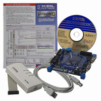
BOARD EVAL/ULINK JTAG LPC210XARM
Manufacturer
NXP Semiconductors
Series
Keilr
Type
ARM7 Processor, Microcontrollerr
Datasheet
1.MCB2100U.pdf
(14 pages)
Specifications of MCB2100+U
Contents
Evaluation Board, ULINK JTAG, Debugger and Software
For Use With/related Products
LPC2114,2119,2124,2129,2194
Lead Free Status / RoHS Status
Not applicable / Not applicable
Other names
568-1755
OM10046
OM10046


NXP Semiconductors
AN10302_4
Application note
4.2.1 Enabling ISP mode with the IAR/Philips Kickstart card
Table 2.
[1]
[2]
The Kickstart Card evaluation board was designed to utilize the RTS/DTR control of reset
and P0.14 as featured in the Philips LPC2000 Flash utility.
To setup the Kickstart Card for ISP programming set the jumpers: JP7, JP8, JP2 and JP4.
Remove jumper JP6. Connect the PC serial port to P0 (UART0) of the Kickstart Card and
start the LPC2000 Flash Utility. Check the “Use DTR/RTS……” box and continue.
Jumper
JP1
JP2
JP3
JP4
JP5
JP6
JP7
JP8
P0.14 and external interrupt one share the same pin; therefore this button may also be used for manual
entry into ISP mode by pressing it during a reset.
This jumper, when in the JTAG1 position, will cause the microcontroller to enter JTAG debug mode after
reset. Therefore, when using ISP, this jumper must be removed or placed in the JTAG2 position.
IAR/Philips Kickstart card jumper functions
Function
Enables external interrupt zero via the push-button
Enables ISP and external interrupt one
Connects P0.9/RxD1 (UART1) to the MAX3232
Connects P0.1/RxD0 (UART0) to the MAX3232
Enables external interrupt zero via the push-button
Primary/Secondary JTAG select
Enable DTR/RTS control of P0.14
Enable DTR/RTS control of RESET
Rev. 04 — 12 October 2006
[2]
Using the Philips LPC2000 Flash utility
[1]
AN10302
© NXP B.V. 2006. All rights reserved.
12 of 14
Related parts for MCB2100+U
Image
Part Number
Description
Manufacturer
Datasheet
Request
R

Part Number:
Description:
NXP Semiconductors designed the LPC2420/2460 microcontroller around a 16-bit/32-bitARM7TDMI-S CPU core with real-time debug interfaces that include both JTAG andembedded trace
Manufacturer:
NXP Semiconductors
Datasheet:

Part Number:
Description:
NXP Semiconductors designed the LPC2458 microcontroller around a 16-bit/32-bitARM7TDMI-S CPU core with real-time debug interfaces that include both JTAG andembedded trace
Manufacturer:
NXP Semiconductors
Datasheet:
Part Number:
Description:
NXP Semiconductors designed the LPC2468 microcontroller around a 16-bit/32-bitARM7TDMI-S CPU core with real-time debug interfaces that include both JTAG andembedded trace
Manufacturer:
NXP Semiconductors
Datasheet:
Part Number:
Description:
NXP Semiconductors designed the LPC2470 microcontroller, powered by theARM7TDMI-S core, to be a highly integrated microcontroller for a wide range ofapplications that require advanced communications and high quality graphic displays
Manufacturer:
NXP Semiconductors
Datasheet:
Part Number:
Description:
NXP Semiconductors designed the LPC2478 microcontroller, powered by theARM7TDMI-S core, to be a highly integrated microcontroller for a wide range ofapplications that require advanced communications and high quality graphic displays
Manufacturer:
NXP Semiconductors
Datasheet:
Part Number:
Description:
The Philips Semiconductors XA (eXtended Architecture) family of 16-bit single-chip microcontrollers is powerful enough to easily handle the requirements of high performance embedded applications, yet inexpensive enough to compete in the market for hi
Manufacturer:
NXP Semiconductors
Datasheet:
Part Number:
Description:
The XA-S3 device is a member of Philips Semiconductors? XA(eXtended Architecture) family of high performance 16-bitsingle-chip microcontrollers
Manufacturer:
NXP Semiconductors
Datasheet:

Part Number:
Description:
The NXP BlueStreak LH75401/LH75411 family consists of two low-cost 16/32-bit System-on-Chip (SoC) devices
Manufacturer:
NXP Semiconductors
Datasheet:
Part Number:
Description:
The NXP LPC3130/3131 combine an 180 MHz ARM926EJ-S CPU core, high-speed USB2
Manufacturer:
NXP Semiconductors
Datasheet:
Part Number:
Description:
The NXP LPC3141 combine a 270 MHz ARM926EJ-S CPU core, High-speed USB 2
Manufacturer:
NXP Semiconductors
Part Number:
Description:
The NXP LPC3143 combine a 270 MHz ARM926EJ-S CPU core, High-speed USB 2
Manufacturer:
NXP Semiconductors

Part Number:
Description:
The NXP LPC3152 combines an 180 MHz ARM926EJ-S CPU core, High-speed USB 2
Manufacturer:
NXP Semiconductors
Part Number:
Description:
The NXP LPC3154 combines an 180 MHz ARM926EJ-S CPU core, High-speed USB 2
Manufacturer:
NXP Semiconductors

Part Number:
Description:
Standard level N-channel enhancement mode Field-Effect Transistor (FET) in a plastic package using NXP High-Performance Automotive (HPA) TrenchMOS technology
Manufacturer:
NXP Semiconductors
Datasheet: