AD9958/PCB Analog Devices Inc, AD9958/PCB Datasheet - Page 26
AD9958/PCB
Manufacturer Part Number
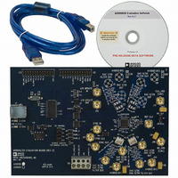
AD9958/PCB
Description
BOARD EVALUATION FOR AD9958
Manufacturer
Analog Devices Inc
Datasheet
1.AD9958BCPZ.pdf
(44 pages)
Specifications of AD9958/PCB
Design Resources
Low Jitter Sampling Clock Generator for High Performance ADCs Using AD9958/9858 and AD9515 (CN0109) Phase Coherent FSK Modulator (CN0186)
Lead Free Status / RoHS Status
Contains lead / RoHS non-compliant
Available stocks
Company
Part Number
Manufacturer
Quantity
Price
Company:

Part Number:
AD9958/PCBZ
Manufacturer:
Analog Devices Inc
Quantity:
135


AD9958
This load and countdown operation continues for as long as the
timer is enabled. However, the count can be reloaded before
reaching 1 by either of the following two methods:
•
•
Frequency Linear Sweep Example: AFP Bits = 10
In the following example, the modulation level bits (FR1[9:8]) = 00,
the linear sweep enable bit (CFR[14]) = 1, and the linear sweep
no-dwell bit (CFR[15]) = 0.
In linear sweep mode, when the profile pin transitions from low
to high, the RDW is applied to the input of the sweep accumulator
and the RSRR register is loaded into the sweep rate timer.
The RDW accumulates at the rate given by the rising sweep
ramp rate (RSRR) bits until the output is equal to the CW1
register value. The sweep is then complete, and the output is
held constant in frequency.
Method 1 is to change the profile pin. When the profile pin
changes from Logic 0 to Logic 1, the rising sweep ramp rate
(RSRR) register value is loaded into the ramp rate timer,
which then proceeds to count down as normal. When the
profile pin changes from Logic 1 to Logic 0, the falling sweep
ramp rate (FSRR) register value is loaded into the ramp
rate timer, which then proceeds to count down as normal.
Method 2 is to set the CFR[14] bit and issue an I/O update.
If sweep is enabled and CFR[14] is set, the ramp rate timer
loads the value determined by the profile pin. If the profile
pin is high, the ramp rate timer loads the RSRR; if the profile
pin is low, the ramp rate timer loads FSRR.
LOAD CONTROL
RDW
FDW
RATE TIME
LOGIC
PROFILE PIN
MUX
0
1
8-BIT LOADABLE DOWN COUNTER
32
0
RAMP RATE TIMER:
FSRR
0
MUX
0
MUX
1
RSRR
8
1
32
PROFILE PIN
Figure 37. Linear Sweep Block Diagram
32
ACCUMULATOR RESET
Rev. A | Page 26 of 44
LOGIC
SWEEP ACCUMULATOR
Z
–1
When the profile pin transitions from high to low, the FDW is
applied to the input of the sweep accumulator and the FSRR bits
are loaded into the sweep rate timer.
The FDW accumulates at the rate given by the falling sweep ramp
rate (FSRR) until the output is equal to the CFTW0 register
(Register 0x04) value. The sweep is then complete, and the output
is held constant in frequency.
See Figure 37 for the linear sweep block diagram. Figure 39
depicts a frequency sweep with no-dwell mode disabled. In this
mode, the output follows the state of the profile pin. A phase or
amplitude sweep works in the same manner.
LINEAR SWEEP NO-DWELL MODE
If the linear sweep no-dwell bit is set (CFR[15]), the rising sweep is
started in an identical manner to the dwell linear sweep mode;
that is, upon detecting Logic 1 on the profile input pin, the rising
sweep action is initiated. The word continues to sweep up at the
rate set by the rising sweep ramp rate at the resolution set by the
rising delta word until it reaches the terminal value. Upon reaching
the terminal value, the output immediately reverts to the starting
point and remains until Logic 1 is detected on the profile pin.
Figure 38 shows an example of the no-dwell mode. The points
labeled A indicate where a rising edge is detected on the profile
pin, and the points labeled B indicate where the AD9958 has
determined that the output has reached E0 and reverts to S0.
The falling sweep ramp rate bits (LSRR[15:8]) and the falling
delta word bits (FDW[31:0]) are unused in this mode.
32
0
KEEP SWEEP BETWEEN
MUX
0
1
LIMIT LOGIC TO
S0 AND E0
MUX
0
1
SWEEP ADDER
CW1
CFTW0
32
32
32
Related parts for AD9958/PCB
Image
Part Number
Description
Manufacturer
Datasheet
Request
R

Part Number:
Description:
BOARD EVALUATION FOR AD9958
Manufacturer:
Analog Devices Inc
Datasheet:


Part Number:
Description:
±1.7g Dual-Axis IMEMS Accelerometer Evaluation Board
Manufacturer:
Analog Devices Inc
Datasheet:

Part Number:
Description:
Inertial Sensor Evaluation System
Manufacturer:
Analog Devices Inc
Datasheet:
Part Number:
Description:
Manufacturer:
Analog Devices Inc
Datasheet:
Part Number:
Description:
Manufacturer:
Analog Devices Inc
Datasheet:
Part Number:
Description:
Manufacturer:
Analog Devices Inc
Datasheet:
Part Number:
Description:
Manufacturer:
Analog Devices Inc
Datasheet:
Part Number:
Description:
Manufacturer:
Analog Devices Inc
Datasheet:
Part Number:
Description:
Manufacturer:
Analog Devices Inc
Datasheet:
Part Number:
Description:
Manufacturer:
Analog Devices Inc
Datasheet:
Part Number:
Description:
Manufacturer:
Analog Devices Inc
Datasheet:
Part Number:
Description:
Manufacturer:
Analog Devices Inc
Datasheet: