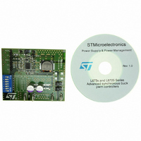
EVAL6730 STMicroelectronics, EVAL6730 Datasheet - Page 30

EVAL6730
Manufacturer Part Number
EVAL6730
Description
EVAL BOARD FOR L6730XX
Manufacturer
STMicroelectronics
Type
Motor / Motion Controllers & Driversr
Datasheets
1.L6730TR.pdf
(52 pages)
2.L6730DTR.pdf
(50 pages)
3.EVAL6730.pdf
(9 pages)
4.EVAL6732.pdf
(43 pages)
Specifications of EVAL6730
Main Purpose
DC/DC, Step Down
Outputs And Type
1, Non-Isolated
Power - Output
66W
Voltage - Output
3.3V
Current - Output
20A
Voltage - Input
4.5 ~ 14V
Regulator Topology
Buck
Frequency - Switching
400kHz
Board Type
Fully Populated
Utilized Ic / Part
L6730
Input Voltage
8 V to 52 V
Product
Power Management Modules
Lead Free Status / RoHS Status
Lead free / RoHS Compliant
For Use With/related Products
L6208
Other names
497-5501
Available stocks
Company
Part Number
Manufacturer
Quantity
Price
AN1451 APPLICATION NOTE
3
Application Data
Rotation Speed:
Winding peak Current: 1A
Maximum Ripple:
Supply Voltage:
Sequence:
3.1 Decay mode, sensing resistors and reference voltage.
The first step is choosing the decay type. Let's suppose to implement slow decay, which allows lower power
dissipation, lower ripple and avoids voltages below GND at output pins during recirculation. Referring to approx-
imated formulae in Figure 25, it's possible to calculate the Duty-Cycle (D), the Switching Frequency (f
Current Ripple ( I). With a 15 µs off-time, we will have:
D
(1.5µs), so slow decay can be used.
The bulk capacitor need to withstand at least 24V + 5% + 25%
voltage ripple of 200mV, the capacitor ESR should be lower than 200mV / 1A = 200m ; the AC current capa-
bility should be about 1A.
Providing a reference voltage of 0.5V, 0.5 sensing resistor are needed. In slow decay mode the resistors pow-
er rating is about P
charge pump uses recommended components (1N4148 diodes, ceramic capacitors and a 100 resistor to re-
duce EMI).
R = 18k , C = 1.2 nF are connected to the RC pins, obtaining t
placed, and the pin is driven by the µC through a 100k resistor. With these values, in case of short circuit be-
tween two OUT pins or an OUT pin and GND, the PowerDMOS turns off after about 1µs, and t
Figure 33. Application Example.
With Wave Drive selected, referring to Figure 24, Figure 25, Figure 26, the dissipating power is about 1.36 W.
If the ambient temperature is lower than 50°C, with 4cm
estimated junction temperature is about 123°C. Using more copper area or a PowerDIP package will reduce the
junction temperature.
30/43
63%, f
APPLICATION EXAMPLE
Logic Supply
+
0.25 W 1%
-
0.25 W 1%
5 V
SW
18 k
2 k
25kHz, I
Custom Logic
R
V
µC
ref
or
= 0.5 V
300 rpm (f
50mA
24V ±5%
Wave Mode
I
rms
2
29mA. The on-time is t
Ceramic
· R
100 k
5.6 nF
SENSE
CK
= 1kHz)
CONTROL
CW / CCW
CLOCK
RESET
HALF / FULL
EN
V
OUT
refA
Ceramic
· D
47nF
1A
OUT
V
18 k
refB
5%
2A
OUT
0.32W. Two 1
1B
OUT
RC
A
Motor Data
Winding Resistance:
Winding Inductance:
Step Angle:
Maximum BEMF at 300rpm: 15V
2B
Ceramic
Stepper Motor
1.2 nF
L6208
ON
18 k
2-Phase
V
5%
BOOT
= D / f
1N4148
0.25W
100
2
RC
of copper area on the PCB and a SO24 package, the
B
CP
Ceramic
1.2 nF
10nF 50V
SW
Ceramic
1N4148
GND
- 0.25W - 1% resistors in parallel are used. The
GND
OFF
V
32V. A 50V capacitor will be used. Allowing a
SA
25µs, which is far from the minimum allowed
GND
SENSE
SENSE
V
SB
GND
220nF 25V
Ceramic
A
B
16µs. On the EN pin a 5.6nF has been
1 , 0.25 W,
4 X
1%
6.6
7.9mH
1.8°/step
ESR<200m
100µF 50V
100nF 50V
Ceramic
DISABLE
V
S
+
= 24 V
-
SW
240µs.
), the


