EVAL6730 STMicroelectronics, EVAL6730 Datasheet - Page 8
EVAL6730
Manufacturer Part Number
EVAL6730
Description
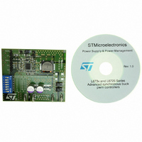
EVAL BOARD FOR L6730XX
Manufacturer
STMicroelectronics
Type
Motor / Motion Controllers & Driversr
Datasheets
1.L6730TR.pdf
(52 pages)
2.L6730DTR.pdf
(50 pages)
3.EVAL6730.pdf
(9 pages)
4.EVAL6732.pdf
(43 pages)
Specifications of EVAL6730
Main Purpose
DC/DC, Step Down
Outputs And Type
1, Non-Isolated
Power - Output
66W
Voltage - Output
3.3V
Current - Output
20A
Voltage - Input
4.5 ~ 14V
Regulator Topology
Buck
Frequency - Switching
400kHz
Board Type
Fully Populated
Utilized Ic / Part
L6730
Input Voltage
8 V to 52 V
Product
Power Management Modules
Lead Free Status / RoHS Status
Lead free / RoHS Compliant
For Use With/related Products
L6208
Other names
497-5501
Available stocks
Company
Part Number
Manufacturer
Quantity
Price


AN1451 APPLICATION NOTE
2.5 Sensing Resistors
Each motor winding current is flowing through the corresponding sensing resistor, causing a voltage drop that
is used, by the logic, to control the peak value of the load current. Two issues must be taken into account when
choosing the R
– The sensing resistor dissipates energy and provides dangerous negative voltages on the SENSE pin
– The voltage drop across R
A good compromise is calculating the sensing resistor value so that the voltage drop, corresponding to the peak
current in the load (I
It should be clear that sensing resistor must absolutely be non-inductive type in order to avoid dangerous neg-
ative spikes on SENSE pins. Wire-wounded resistors cannot be used here, while Metallic film resistors are rec-
ommended for their high peak current capability and low inductance. For the same reason the connections
between the SENSE pins, C6, C7, V
(see also the Layout Considerations section).
The average power dissipated by the sensing resistor is:
D is the duty-cycle of the PWM current control, I
Nevertheless, sensing resistor power rating should be chosen taking into account the peak value of the dissi-
pated power:
where I
Using multiple resistors in parallel will help obtaining the required power rating with standard resistors, and re-
duce the inductance.
R
The following table shows R
examples of current peak values.
8/43
SENSE
during the current recirculation. For this reason the resistance of this component should be kept low.
comparator. The lower is the R
and to the input offset of the current sense comparator: too small values of R
Fast Decay Recirculation: P
Slow Decay Recirculation: P
pk
tolerance reflects on the peak current error: 1% resistors should be preferred.
is the peak value of the load current.
0.5
1.5
I
pk
1
2
SENSE
peak
value:
), is about 0.5 V: R
SENSE
SENSE
R
R
R
SENSE
SENSE
recommended values (to have 0.5V drop on it) and power ratings for typical
I
SA
I
rms
rms
is compared with the reference voltage (on V
, V
0.33
0.25
0.5
2
Value [ ]
2
1
value, the higher is the peak current error due to noise on Vref pin
· R
SB
· R
SENSE
SENSE
and GND pins (see Figure 5) must be taken as short as possible
SENSE
P
R
rms
= 0.5 V / I
I
pk
is the r.m.s. value of the load current.
· D,
2
R
R
S ENSE
SENSE
peak
.
Power Rating [W]
,
0.25
0.75
0.5
1
SENSE
2 X 1 , 0.25W paralleled
3 X 1 , 0.25W paralleled
4 X 1 , 0.25W paralleled
ref
pin) by the internal
must be avoided.
Alternatives
Related parts for EVAL6730
Image
Part Number
Description
Manufacturer
Datasheet
Request
R

Part Number:
Description:
STMicroelectronics [RIPPLE-CARRY BINARY COUNTER/DIVIDERS]
Manufacturer:
STMicroelectronics
Datasheet:
Part Number:
Description:
STMicroelectronics [LIQUID-CRYSTAL DISPLAY DRIVERS]
Manufacturer:
STMicroelectronics
Datasheet:

Part Number:
Description:
BOARD EVAL FOR MEMS SENSORS
Manufacturer:
STMicroelectronics
Datasheet:
Part Number:
Description:
NPN TRANSISTOR POWER MODULE
Manufacturer:
STMicroelectronics
Datasheet:
Part Number:
Description:
TURBOSWITCH ULTRA-FAST HIGH VOLTAGE DIODE
Manufacturer:
STMicroelectronics
Datasheet:
Part Number:
Description:
Manufacturer:
STMicroelectronics
Datasheet:
Part Number:
Description:
DIODE / SCR MODULE
Manufacturer:
STMicroelectronics
Datasheet:
Part Number:
Description:
DIODE / SCR MODULE
Manufacturer:
STMicroelectronics
Datasheet:
Part Number:
Description:
Search -----> STE16N100
Manufacturer:
STMicroelectronics
Datasheet:
Part Number:
Description:
Search ---> STE53NA50
Manufacturer:
STMicroelectronics
Datasheet:
Part Number:
Description:
NPN Transistor Power Module
Manufacturer:
STMicroelectronics
Datasheet:
Part Number:
Description:
DIODE / SCR MODULE
Manufacturer:
STMicroelectronics
Datasheet: