UP2-DEVKIT/UNIV Altera, UP2-DEVKIT/UNIV Datasheet
UP2-DEVKIT/UNIV
Specifications of UP2-DEVKIT/UNIV
Available stocks


Related parts for UP2-DEVKIT/UNIV


UP2-DEVKIT/UNIV Summary of contents
Page 1
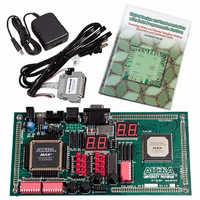
... UP2 Education Board The UP2 Education Board is a stand-alone experiment board based on a FLEX Quartus II software, the board provides a superior platform for learning digital logic design using industry-standard development tools and PLDs ...
Page 2
... For more information on MAX 7000 devices the MAX 7000 Programmable Logic Device Family Data Sheet. ByteBlaster II Parallel Port Download Cable Designs can be easily and quickly downloaded into the UP2 Education Board using the ByteBlaster II download cable, which is a hardware interface to a standard parallel port. This cable sends programming or ...
Page 3
... Education Board. Because design changes are downloaded directly to the devices on the board, prototyping is easy and multiple design iterations can be accomplished in quick succession. UP2 Education The UP2 Education Board, shown in Figure 1, contains the features described in this section. Board Description Figure 1. UP2 Education Board Block Diagram ...
Page 4
... JTAG_IN Header The 10-pin female plug on the ByteBlaster II download cable connects with the JTAG_IN 10-pin male header on the UP2 Education Board. The board provides power and ground to the ByteBlaster II download cable. Data is shifted into the devices via the TDI pin and shifted out of the devices via the TDO pin ...
Page 5
... TCK LED will modulate to indicate that data is transferring. After the device has successfully configured, the CONF_D LED will illuminate. f For information on how to program or configure the EPF10K70, or EPM7128S devices, see “Programming or Configuring Devices” on page 18. Altera Corporation University Program UP2 Education Kit User Guide TDI Table 2. JTAG Jumper Settings Desired Action C1 & ...
Page 6
... PLCC package connect to one of the 22-pin, dual-row 0.1-inch female headers. The pin numbers for the EPM7128S device are printed on the UP2 Education Board (an “X” indicates an unassigned pin). Table 3 lists the pin numbers for the four female headers: P1, P2, P3, and P4 ...
Page 7
... I/O pin of the EPM7128S device. The switch output is set to logic 1 when the switch is open and set to logic 0 when the switch is closed. Altera Corporation University Program UP2 Education Kit User Guide Note (1) P2 Inside Outside ...
Page 8
... University Program UP2 Education Kit User Guide D1 through D16 LEDs The UP2 Education Board contains 16 LEDs that are pulled-up with a 330-Ω resistor. An LED is illuminated when a logic 0 is applied to the female header associated with the LED. LEDs D1 through D8 are connected in the same sequence to the female headers (i.e connected to position 1, and D2 is connected to position 2, etc ...
Page 9
... MAX_EXPANSION is a dual row of 0.1-inch-spaced holes for accessing signal I/O pins and global signals on the EPM7128S device, power, and ground. Figure 5 shows the numbering convention for the holes. Figure 5. MAX_EXPANSION Numbering Convention Altera Corporation University Program UP2 Education Kit User Guide Table 4. MAX_DIGIT Segment I/O Connections Display Segment a b ...
Page 10
... University Program UP2 Education Kit User Guide Table 5 lists the signal names and the EPM7128S device pins connected to each hole. 10 Table 5. MAX_EXPANSION Signal Names & Device Connections Hole Number Signal/Pin 1 RAW 3 VCC 5 VCC 7 No Connect 9 No Connect 11 No Connect 13 OE1/ VCC ...
Page 11
... FLEX 10K Device The UP2 Education Board provides the following resources for the FLEX 10K device. The pins from the FLEX 10K device are pre-assigned to switches and LEDs on the board. ■ ■ ■ ■ ■ ■ ■ ■ ■ FLEX_PB1 & FLEX_PB2 Push Buttons FLEX_PB1 and FLEX_PB2 are two push buttons that provide active-low signals to two general-purpose I/O pins on the FLEX 10K device ...
Page 12
... University Program UP2 Education Kit User Guide FLEX_DIGIT Display FLEX_DIGIT is a dual-digit, seven-segment display connected directly to the FLEX 10K device. Each LED segment on the display can be illuminated by driving the connected FLEX 10K device I/O pin with a logic 0. See Figure 4 on page 8 for the name of each segment. Table 7 lists the pin assignment for each segment ...
Page 13
... I/O pins and global signals on the FLEX 10K device, power, and ground. Figure 6 shows the numbering convention for these holes. Altera Corporation University Program UP2 Education Kit User Guide Table 8. D-Sub Connections Signal D-Sub Connector Pin ...
Page 14
... University Program UP2 Education Kit User Guide Figure 6. FLEX_EXPAN_A, FLEX_EXPAN_B & FLEX_EXPAN_C Numbering Convention Tables 10 through 12 list the signal name and the FLEX 10K device pin connected to each hole Education Board AN_ 1113 Altera Corporation ...
Page 15
... Altera Corporation University Program UP2 Education Kit User Guide Table 10. FLEX_EXPAN_A Signal Names & Device Connections Hole Number Signal/Pin 1 RAW 3 VCC 5 VCC 7 No Connect 9 DI2/92 11 DI4/212 13 DEV_OE/213 100 57 VCC 59 VCC Hole Number Signal/Pin 2 GND 4 GND 6 GND 8 DI1/90 10 DI3/210 12 DEV_CLR/209 14 DEV_CLK2/211 16 46 ...
Page 16
... University Program UP2 Education Kit User Guide 16 Table 11. FLEX_EXPAN_B Signal Names & Device Connections Hole Number Signal/Pin 1 RAW 3 VCC 5 VCC 7 No Connect 9 DI2/92 11 DI4/212 13 DEV_OE/213 15 109 17 111 19 114 21 116 23 118 25 120 27 127 29 129 31 132 33 134 35 137 37 139 39 142 41 144 43 147 45 149 ...
Page 17
... Windows 98/2000 and Windows NT 4.0 operating systems. Installation After installation, students can register to obtain a license via the Altera world-wide web site at the following URL: http://www.altera.com/support/licensing/lic-university.html. Altera Corporation University Program UP2 Education Kit User Guide Table 12. FLEX_EXPAN_C Signal Names & Device Connections Hole Number Signal/Pin 1 RAW ...
Page 18
... JTAG programming or Configuring options in the Quartus II software, and connecting the ByteBlaster II download cable to the PC’s parallel port and to the JTAG_IN connector on Devices the UP2 Education Board. This section describes how to set these options. ■ ■ ■ ■ ...
Page 19
... EPM7128S device in a JTAG chain. f For more information on how to use the Quartus II software, see the Quartus II Help Altera Corporation University Program UP2 Education Kit User Guide TDI TDO Turn on the Multi-Device JTAG Chain command (JTAG menu) in the Quartus II Programmer to program a device. Follow this procedure even if you are only programming one device ...
Page 20
... Connecting the ByteBlaster II Download Cable for the EPF10K70 Configuration Attach the ByteBlaster II cable directly to the PC’s parallel port and to the JTAG_IN connector on the UP2 Education Board. For more information on setting up the ByteBlaster II cable, see the ByteBlaster II Parallel Port Download Cable Data Sheet. ...
Page 21
... Altera Corporation University Program UP2 Education Kit User Guide Turn on the Multi-Device JTAG Chain command (JTAG menu) in the Quartus II Programmer to configure the EPF10K70 device. Follow this step even if you are only programming one device. Choose Multi-Device JTAG Chain Setup (JTAG menu). ...
Page 22
... Connecting the ByteBlaster II Download Cable for Configuring & Programming Both Devices Attach the ByteBlaster II cable directly to the PC’s parallel port and to the JTAG_IN connector on the UP2 Education Board. For more information on setting up the ByteBlaster II cable, see the ByteBlaster II Parallel Port Download Cable Data Sheet. ...
Page 23
... Click Configure in the Quartus II Programmer to configure all FLEX Connect Multiple UP2 Education Boards Together in a Chain This section describes the procedures for connecting multiple UP2 Education Boards together (i.e., how to set the on-board jumpers, connect the ByteBlaster II download cable, and set options in the Quartus II software) ...
Page 24
... TDI, TDO, DEVICE, and BOARD for all boards except the last board in the chain as shown in Figure 10. Figure 10. Jumper Settings for All Boards Except the Last Board in the Chain The last UP2 Education Board in the chain can configure and program one or both devices. However, the BOARD jumper must be set as shown in Figure 11. ...
Page 25
... For the VGA monitor to work properly, it must receive data at specific times with specific pulses. Horizontal and vertical synchronization pulses must occur at specified times to synchronize the monitor while it is Altera Corporation University Program UP2 Education Kit User Guide 640 pixels (0,0) (640, 480) ...
Page 26
... University Program UP2 Education Kit User Guide receiving color data. Figures 13 and 14 show the timing waveforms for the color information with respect to the horizontal and vertical synchronization signals. Figure 13. Horizontal Refresh Cycle RED, GREEN, BLUE HORIZ_SYNC Parameters 31.77 µs Time 3.77 µs ...
Page 27
... Once the timing of the horizontal and vertical synchronization signals is accurate, the monitor only needs to keep track of the current location can send the correct color data to the pixel. Altera Corporation University Program UP2 Education Kit User Guide 480 Horizontal Refresh Cycles Q ...
Page 28
... University Program UP2 Education Kit User Guide Mouse You can connect a mouse to the UP2 Education Board via the 6-pin mini-DIN connector. The data is sent using a synchronous serial protocol, Interface and the transmission is controlled by the CLK and DATA signals. During non-transmission, CLK is at logic 1 and DATA can be either logic 0 or Operation logic 1 ...
Page 29
... Notes: Altera Corporation 29 ...
Page 30
... University Program UP2 Education Kit User Guide ® Altera, MAX II, MAX 7000S, Quartus II, EPM7128S, FLEX, FLEX 10K, EPF10K20, EPF10K70, ByteBlaster II, EPC1, and AHDL are trademarks and/or service marks of Altera Corporation in the United States and other 101 Innovation Drive countries. Altera acknowledges the trademarks of other organizations for their respective products or services San Jose, CA 95134 mentioned in this document ...