SP4-L2-DC24V Panasonic Electric Works, SP4-L2-DC24V Datasheet - Page 7
SP4-L2-DC24V
Manufacturer Part Number
SP4-L2-DC24V
Description
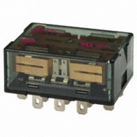
RELAY PWR LATCH 10A 24VDC PLUGIN
Manufacturer
Panasonic Electric Works
Series
SPr
Type
Power Relayr
Datasheet
1.SP-MA.pdf
(7 pages)
Specifications of SP4-L2-DC24V
Relay Type
General Purpose
Contact Form
4PDT (4 Form C)
Contact Rating (current)
10A
Switching Voltage
250VAC
Coil Type
Latching, Dual Coil
Coil Current
12.5mA
Coil Voltage
24VDC
Turn On Voltage (max)
16.8 VDC
Mounting Type
Socket
Termination Style
Quick Connect - .187" (4.7mm)
Circuit
4PDT (4 Form C)
Contact Rating @ Voltage
10A @ 250VAC
Control On Voltage (max)
16.8 VDC
Relay Construction
Latching Double Coil
Contact Arrangement
4PDT
Coil Voltage Dc
24V
Voltage Rating (vdc)
30V
Voltage Rating (vac)
250V
Coil Resistance
1.92kohm
Pick-up Voltage (max)
16.8VDC
Maximum Power Rating
300W/2.5KVA
Operate Time
30ms
Contact Current Rating
10A
Contact Material
AgSnO2
Coil Suppression Diode
No
Push To Test Button
No
Led Indicator
No
Seal
Unsealed
Product Height (mm)
22mm
Product Depth (mm)
25.6mm
Product Length (mm)
51mm
Operating Temp Range
-50C to 60C
Pin Count
16
Mounting Style
Plug-In
Package / Case
Dust Cover
Lead Free Status / RoHS Status
Lead free / RoHS Compliant
Control Off Voltage (min)
-
Lead Free Status / Rohs Status
Compliant
Available stocks
Company
Part Number
Manufacturer
Quantity
Price
Company:

Part Number:
SP4-L2-DC24V
Manufacturer:
PANASONIC
Quantity:
12 000


SP
Direct chassis mounting possible, and applicable to DIN rail.
DIMENSIONS
Mounting hole diagram
Use method
1. Both the SP relay 2 Form C and
4 Form C can be mounted to the
mounting slats.
2. Use the mounting slats either by
attaching them directly to the chassis, or
by mounting with a DIN rail.
(A) When attaching directly to chassis
Use two M3 screws.
For the mounting pitch, refer to the
specification diagram.
(B) When mounting on a DIN rail
Use a 35mm
(DIN46277).
The mounting method should be as
indicated in the diagram at right.
CAD Data
18.4
.724
Panel cutout
1.378inch
18.4
.724
2.252
57.2
Tolerance: 0.1
(mm inch)
2-3.2 dia. hole
2-.126 dia. hole
wide DIN rail
.984
23.2
.913
25
.004
The CAD data of the products with a
All Rights Reserved © COPYRIGHT Panasonic Electric Works Co., Ltd.
Method for mounting on DIN rail
Fit into mounting
grooves.
Press
ACCESSORIES
Press relay in
Fit in
TYPES
CAD Data
Mounting board
To remove the
relay, press down
the mounting slats
so the claws move
to the outside.
Product name
Mounting
slat
DIN rail
Fig. 1
Fig. 2
Fig. 3
mark can be downloaded from: http://panasonic-electric-works.net/ac
(1) First fit the arc shaped claw of the
mounting slat into the DIN rail.
(2) Press on the side as shown in the
diagram below.
(3) Fit in the claw part on the opposite
side.
Precautions for use
When mounting to a DIN rail, use a
commercially available fastening bracket
if there is a need to stop sliding of the
mounting slat in the rail direction.
MOUNTING BOARD
SP RELAYS
Part No.
SP-MA
Related parts for SP4-L2-DC24V
Image
Part Number
Description
Manufacturer
Datasheet
Request
R

Part Number:
Description:
RELAY PWR LATCH 10A 5VDC PLUG-IN
Manufacturer:
Panasonic Electric Works
Datasheet:
Part Number:
Description:
RELAY LATCHING 10A 12VDC PLUG-IN
Manufacturer:
Panasonic Electric Works
Datasheet:
Part Number:
Description:
RELAY PWR LATCH 10A 3VDC PLUG-IN
Manufacturer:
Panasonic Electric Works
Datasheet:
Part Number:
Description:
RELAY PWR LATCH 10A 6VDC PLUG-IN
Manufacturer:
Panasonic Electric Works
Datasheet:
Part Number:
Description:
RELAY PWR LATCH 10A 48VDC PLUGIN
Manufacturer:
Panasonic Electric Works
Datasheet:

Part Number:
Description:
Audio & Signal Transformers 200K/1K CT XFMR PRI/SEC RED SPEC
Manufacturer:
Triad Magnetics

Part Number:
Description:
Manufacturer:
Panasonic Electric Works
Datasheet:
Part Number:
Description:
Manufacturer:
Panasonic Electric Works
Datasheet:

Part Number:
Description:
CONN SOCKET P4 .4MM 50POS SMD
Manufacturer:
Panasonic Electric Works
Datasheet:
Part Number:
Description:
CONN SOCKET .8MM 16POS SMD
Manufacturer:
Panasonic Electric Works
Datasheet:
Part Number:
Description:
CONN HEADER .8MM 16POS SMD
Manufacturer:
Panasonic Electric Works
Datasheet:
Part Number:
Description:
CONN SOCKET .8MM 20POS SMD
Manufacturer:
Panasonic Electric Works
Datasheet:
Part Number:
Description:
CONN SOCKET .8MM 20POS SMD
Manufacturer:
Panasonic Electric Works
Datasheet:
Part Number:
Description:
CONN HEADER .8MM 20POS SMD
Manufacturer:
Panasonic Electric Works
Datasheet:
Part Number:
Description:
CONN SOCKET .8MM 22POS SMD
Manufacturer:
Panasonic Electric Works
Datasheet: