EEE-HA1C470AP Panasonic - ECG, EEE-HA1C470AP Datasheet
EEE-HA1C470AP
Specifications of EEE-HA1C470AP
PCE4658TR


Related parts for EEE-HA1C470AP


EEE-HA1C470AP Summary of contents
Page 1
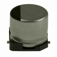
... V Design and specifi cations are each subject to change without notice. Ask factory for the current technical specifi cations before purchase and/or use. Should a safety concern arise regarding this product, please be sure to contact us immediately. Aluminum Electrolytic Capacitors/ HA Hight-temperature assuranceize ...
Page 2
... EEEHAA471UAP G 270 0.26 EEEHA1A471AP (G) 400 0.35 EEEHAA102UAP B 28 0.16 EEEHA1C100AR (B) 28 0.26 EEEHAC220WAR C 39 0.16 EEEHA1C220AR (C) 35 0.26 EEEHAC330WAR (C) 39 0.26 EEEHAC470WAR D 70 0.16 EEEHA1C470AP (D) 70 0.26 EEEHAC101WAP D8 105 0.20 EEEHAC221XAP (F) 150 0.20 EEEHAC221UAP G 210 0.20 EEEHA1C221AP (F) 170 0.20 ...
Page 3
... G 160 0.14 EEEHA1V101AP (F) 170 0.14 EEEHAV221UAP G 210 0.14 EEEHA1V221AP (G) 250 0.30 EEEHAV331UAP B 1 0.12 EEEHA1HR10AR B 2 0.12 EEEHA1HR22AR B 3 0.12 EEEHA1HR33AR B 5 0.12 EEEHA1HR47AR B 10 0.12 EEEHA1H1R0AR B 16 0.12 EEEHA1H2R2AR B 16 0.12 EEEHA1H3R3AR C 23 0.12 EEEHA1H4R7AR D 35 0.12 EEEHA1H100AP E 70 0.12 ...