@Super low ESR, impedance and high heat resistance have been obtained by using
@Rated voltage range : 2.5 to 25V
@Suitable for DC-DC converters, voltage regulators and decoupling applications used on
@RoHS Compliant
?SPECIFICATIONS
*Note : If any doubt arises, measure the leakage current after the following voltage treatment.
?PART NUMBERING SYSTEM
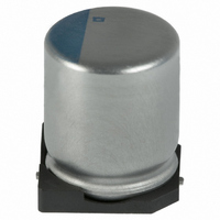
?DIMENSIONS [mm]
@Terminal Code : A
Category
Temperature Range
Rated Voltage Range
Capacitance Tolerance
Surge Voltage
Leakage Current
Dissipation Factor
(tane)
Low Temperature
Characteristics
(Max. Impedance Ratio)
Endurance
Bias Humidity
Surge Voltage
Failure Rate
A P X A
conductive polymer as electrolyte
computer motherboards etc.
1
Please refer to "Product code guide (conductive polymer type)"
2
Note : L+0.1/-0.2 for F46
Items
3
Voltage treatment : DC rated voltage is applied to the capacitors for 120 minutes at 105C.
LP0.3 (Note)
4
LP0.5 for HC0 and JC0
A A A
0.3max.
5
6
CONDUCTIVE POLYMER ALUMINUM SOLID CAPACITORS
7
A R A
8
-55 to +105C
2.5 to 25V
P20% (M)
Rated voltageB1.15 (Rated voltage 2.5 to 20V
Shall not exceed values shown in STANDARD RATINGS.
0.12 max.
Z(-25C)/Z(+20C)[1.15
Z(-55C)/Z(+20C)[1.25
The following specifications shall be satisfied when the capacitors are restored to 20C after the rated voltage is applied for 2,000 hours
(F46 : 1,000 hours) at 105C.
Appearance
Capacitance change
DF (tanE)
ESR
Leakage current
The following specifications shall be satisfied when the capacitors are restored to 20C after subjecting them to the DC rated voltage at
60C, 90 to 95% RH for 1,000 hours(F46 : 500 hours).
Appearance
Capacitance change
DF (tanE)
ESR
Leakage current
The capacitors shall be subjected to 1,000 cycles each consisting of charge with the surge voltage specified at 105C for 30 seconds
through a protective resistor(R=1kO) and discharge for 5 minutes 30 seconds.
Appearance
Capacitance change
DF (tanE)
ESR
Leakage current
0.5% per 1,000 hours maximum (Confidence level 60% at 105C)
9
10
A A A
11
W
AP0.2
12 13
dc
M
dc
14
, case size range : F4B5.2L to F10B12.2L
A A A
15
Capacitance code (ex. 10MF:100,100MF:101)
16 17
No significant damage
[P20% of the initial value
[150% of the initial specified value
[150% of the initial specified value
[The initial specified value
No significant damage
[P20% of the initial value
[150% of the initial specified value
[150% of the initial specified value
[The initial specified value
No significant damage
[P20% of the initial value
[150% of the initial specified value
[150% of the initial specified value
[The initial specified value
G
18
Voltage code (ex. 6.3V:6R3,10V:100)
Size code
Capacitance tolerance code
HC0
D55
E60
F46
F55
F60
H70
J80
JC0
fD
6.3
6.3
6.3
Supplement code
10
10
4
5
8
8
dc
, 25V
Terminal code
12.0
12.2
Taping code
5.2
5.7
4.5
5.2
5.7
6.7
7.7
Series code
L
Size code
(1/2)
Category
dc
) / Rated voltageB1.00 (Rated voltage 23V
10.3
10.3
4.3
5.3
6.6
6.6
6.6
8.3
8.3
A
Characteristics
10.3
10.3
4.3
5.3
6.6
6.6
6.6
8.3
8.3
B
11.0
11.0
5.1
5.9
7.2
7.2
7.2
9.0
9.0
C
0.5 to 0.8
0.5 to 0.8
0.5 to 0.8
0.5 to 0.8
0.5 to 0.8
0.7 to 1.1
0.7 to 1.1
0.7 to 1.1
0.7 to 1.1
W
1.0
1.4
1.9
1.9
1.9
3.1
3.1
4.5
4.5
P
PXA
PXE
Lower ESR
dc
)
CAT. No. E1001K
(at 20C after 2 minutes)
?MARKING
EX) 16V39MF
Surface Mount
(at 20C, 120Hz)
(at 20C, 120Hz)
A
16
(at 100kHz)
39
15L
(at 105C)
V