MAL203026109E3 Vishay, MAL203026109E3 Datasheet - Page 6
MAL203026109E3
Manufacturer Part Number
MAL203026109E3
Description
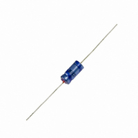
10UF 25V AXIAL ELECTROLYTIC CAP
Manufacturer
Vishay
Series
030 ASr
Datasheet
1.MAL203026109E3.pdf
(9 pages)
Specifications of MAL203026109E3
Capacitance
10µF
Voltage Rating
25V
Tolerance
-10%, +50%
Lifetime @ Temp.
2000 Hrs @ 85°C
Operating Temperature
-40°C ~ 85°C
Features
General Purpose
Ripple Current
50mA
Esr (equivalent Series Resistance)
22.30 Ohm
Impedance
9 Ohm
Mounting Type
Through Hole
Package / Case
Axial, Can
Size / Dimension
0.177" Dia x 0.394" L (4.50mm x 10.00mm)
Lead Free Status / RoHS Status
Lead free / RoHS Compliant
Height
-
Lead Spacing
-
Surface Mount Land Size
-
Other names
22220 030 26109
Q1138264
Q1138264


www.vishay.com
184
030/031 AS
Vishay BCcomponents
EQUIVALENT SERIES RESISTANCE (ESR)
IMPEDANCE (Z
Table 3
ESR
(Ω)
ESR
Z
10
IMPEDANCE VS. CAPACITANCE VALUES AT 10 kHz
10
10
10
ESR
10
0.3
30
20
10
1
+ 20 °C
-1
- 25 °C
- 40 °C
4
3
2
0
10
- 60
T
0
amb
2
= capacitance at 20 °C, 100 Hz
Fig.7 Typical impedance as a function of frequency
- 40
1
2
3
4
5
6
7
8
2
1
3
Fig.5 Typical multiplier of ESR as a function
- 20
10
3
≤ 200
≤ 1200
≤ 3200
)
6.3 V
of ambient temperature
0
20
Curve 1: 1 µF, 63 V, 3.3 x 11 mm
Curve 2: 2.2 µF, 40 V, 3.3 x 11 mm
Curve 3: 4.7 µF,16 V, 3.3 x 11 mm
Curve 4: 10 µF, 25 V, 4.5 x 11 mm
Curve 5: 22 µF, 25 V, 4.5 x 11 mm
Curve 6: 47 µF, 25 V, 6 x 11 mm
Curve 7: 100 µF, 25 V, 6.5 x 11 mm
Curve 8: 220 µF, 10 V, 6.5 x 11 mm
10
4
40
For technical questions contact: aluminumcaps1@vishay.com
≤ 160
≤ 750
≤ 2000
10 V
60
10
Curve 1: 6.3 V
Curve 2: 63 V
Curve 3: 100 V
5
80
T
T
amb
Aluminum Capacitors
2
1
3
amb
100
20 °C
(°C)
≤ 120
≤ 560
≤ 1500
Axial Standard
16 V
120
10
6
Z x C
(Ω)
ESR
ESR
Z
R
10
10
10
10
ESR
≤ 90
≤ 400
≤ 1100
1
(Ω x µF)
2
1
0
25 V
-1
-2
3
1
0
10
10
0
2
= capacitance at 20 °C, 100 Hz
Fig.8 Typical impedance as a function of frequency
1
2
3
4
5
6
Fig.6 Typical multiplier of ESR as a function
10
2
1
3
≤ 70
≤ 300
≤ 900
40 V
3
10
2
of frequency
Curve 1: 22 µF, 63 V, 8 x 11 mm
Curve 2: 47 µF, 40 V, 8 x 11 mm
Curve 3: 150 µF, 25 V, 8 x 18 mm
Curve 4: 330 µF, 16 V, 10 x 18 mm
Curve 5: 470 µF, 16 V, 10 x 25 mm
Curve 6: 1000 µF, 6.3 V, 10 x 25 mm
10
4
≤ 55
≤ 180
≤ 500
63 V
Document Number: 28327
10
3
Revision: 15-Oct-08
10
5
T
T
amb
amb
100 V
≤ 45
≤ 130
≤ 350
20 °C
1
3
2
(°C)
10
10
6
4
Related parts for MAL203026109E3
Image
Part Number
Description
Manufacturer
Datasheet
Request
R

Part Number:
Description:
357-036-542-201 CARDEDGE 36POS DL .156 BLK LOPRO
Manufacturer:
Vishay
Datasheet:
Part Number:
Description:
357-036-542-201 CARDEDGE 36POS DL .156 BLK LOPRO
Manufacturer:
Vishay
Datasheet:
Part Number:
Description:
357-036-542-201 CARDEDGE 36POS DL .156 BLK LOPRO
Manufacturer:
Vishay
Datasheet:
Part Number:
Description:
357-036-542-201 CARDEDGE 36POS DL .156 BLK LOPRO
Manufacturer:
Vishay
Datasheet:
Part Number:
Description:
357-036-542-201 CARDEDGE 36POS DL .156 BLK LOPRO
Manufacturer:
Vishay
Datasheet:
Part Number:
Description:
357-036-542-201 CARDEDGE 36POS DL .156 BLK LOPRO
Manufacturer:
Vishay
Datasheet:
Part Number:
Description:
357-036-542-201 CARDEDGE 36POS DL .156 BLK LOPRO
Manufacturer:
Vishay
Datasheet:
Part Number:
Description:
357-036-542-201 CARDEDGE 36POS DL .156 BLK LOPRO
Manufacturer:
Vishay
Datasheet:
Part Number:
Description:
357-036-542-201 CARDEDGE 36POS DL .156 BLK LOPRO
Manufacturer:
Vishay
Datasheet:
Part Number:
Description:
357-036-542-201 CARDEDGE 36POS DL .156 BLK LOPRO
Manufacturer:
Vishay
Datasheet:
Part Number:
Description:
357-036-542-201 CARDEDGE 36POS DL .156 BLK LOPRO
Manufacturer:
Vishay
Datasheet:
Part Number:
Description:
357-036-542-201 CARDEDGE 36POS DL .156 BLK LOPRO
Manufacturer:
Vishay
Datasheet:
Part Number:
Description:
357-036-542-201 CARDEDGE 36POS DL .156 BLK LOPRO
Manufacturer:
Vishay
Datasheet:
Part Number:
Description:
357-036-542-201 CARDEDGE 36POS DL .156 BLK LOPRO
Manufacturer:
Vishay
Datasheet:
Part Number:
Description:
357-036-542-201 CARDEDGE 36POS DL .156 BLK LOPRO
Manufacturer:
Vishay
Datasheet: