ST203C686MAJ03 AVX Corporation, ST203C686MAJ03 Datasheet - Page 71
ST203C686MAJ03
Manufacturer Part Number
ST203C686MAJ03
Description
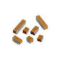
CAP CER 68UF 25V STACKED SMD
Manufacturer
AVX Corporation
Series
TurboCap™r
Specifications of ST203C686MAJ03
Capacitance
68µF
Tolerance
±20%
Temperature Coefficient
X7R
Voltage - Rated
25V
Mounting Type
Surface Mount, MLCC
Operating Temperature
-55°C ~ 125°C
Features
Stacked
Applications
Filtering Switch Mode Power Supplies
Package / Case
6-Stacked SMD, J-Lead
Size / Dimension
0.325" L x 0.300" W (8.26mm x 7.62mm)
Thickness
5.59mm Max
Lead Style
J-Lead
Voltage Rating
25 Volts
Operating Temperature Range
- 55 C to + 125 C
Product
General Type MLCCs
Dielectric Characteristic
X7R
Capacitance Tolerance
± 20%
Capacitor Case Style
DIP
No. Of Pins
6
Capacitor Mounting
SMD
Rohs Compliant
No
Termination Style
Radial
Lead Spacing
6.35 mm
Dimensions
7.62 mm W x 8.26 mm L x 5.59 mm H
Dissipation Factor Df
2.5
Lead Free Status / RoHS Status
Contains lead / RoHS non-compliant
Ratings
-
Lead Spacing
-
Lead Free Status / RoHS Status
Contains lead / RoHS non-compliant
Other names
478-6117


High Voltage Leaded (CH Style)
Radial, Dual-in-Line & ‘L’ Lead SMT
ELECTRICAL SPECIFICATIONS
Temperature Coefficient CECC 30 000, (4.24.1)
1B/C0G:
2C1/X7R: C Temperature Characteristic - ± 15% (0v dc)
Capacitance Test 25ºC
1B/C0G:
2C1/X7R: Measured at 1 VRMS max at 1KHz
Dissipation Factor 25°C
1B/C0G:
2C1/X7R: 2.5% max at 1KHz, 1 VRMS
Insulation Resistance
1B/C0G & 2C1/X7R: 100K megohms or 1000 megohms-μF,
whichever is less
DUAL-IN-LINE
DIMENSIONS
HOW TO ORDER
*Tolerance ± 0.8
70
Code
Style
CH
(0.149)
330 pF to 2.7 μF
1kV to 5kV
-55ºC to +125ºC
1B/C0G and 2C1/X7R Dielectrics
max.
3.8
2.54 (0.100) ±0.5 (0.200)
CH41
CH51
CH61
CH76
CH91
Style
Code
A Temperature Coefficient - 0 ± 30ppm/ºC
Measured at 1 VRMS max at 1KHz (1MHz <100 pF)
0.15% max at 1KHz, 1 VRMS (1MHz for <100 pF)
L2
Size
41
W max.
Voltage Dielectric Capacitance Capacitance
A = 1kV
H = 3kV
K = 5kV
G = 2kV
J = 4kV
Code
A
10.7 (0.421)
14.9 (0.587)
21.6 (0.850)
24.0 (0.944)
L1
9.2 (0.362)
(max)
(0.079)
max.
2.0
L
A = C0G
C = X7R
2.54 (0.100) ±0.5 (0.200)
Code
±1.0 (0.039)
13 (0.512)
C
eg. 105 = 1 μF
(2 significant
digits + no.
106 = 10 μF
107 = 100 μF
Code
104
of zeros)
10.7 (0.421)
13.6 (0.535)
16.6 (0.654)
40.6 (1.598)
8.7 (0.342)
(max)
W
max.
L
C0G: J = ±5%
X7R: K = ±10%
Tolerance
M = ±20%
M = ±20%
K
K = ±10%
P = +100, -0%
W max.
L2
20.3* (0.800)
20.3* (0.800)
10.2 (0.400)
14.0 (0.551)
8.2 (0.323)
(nom)
S
A = Non customized 8 = Varnish
Specification
Dielectric Withstanding Voltage 25°C
130% rated voltage for 5 seconds
Life Test (1000 hrs) CECC 30000 (4.23)
1B/C0G & 2C1/X7R: 120% rated voltage at +125ºC.
Aging
1B/C0G:
2C1/X7R: 2.5%/decade hour
This range of radial, dual-in-line for both through hole and
surface mount products is intended for use in high voltage
power supplies and voltage multiplier circuits. The multilayer
ceramic construction offers excellent volumetric efficiency
compared with other high voltage dielectrics. They are suitable
for both high reliability and industrial applications.
Code
A
3.8 (0.149)
millimeters (inches)
L1
max.
Zero
per side
No. of
Leads
14
Finish
Code
3
4
5
6
S ±0.5 (0.020)
8
0 = Standard
Lead Dia.
Code
Lead width 0.5 (0.020)
Lead thickness 0.254 (0.010)
L1 = L2 ± 0.5 (0.020)
0
2.54 (0.100)
±0.5 (0.200)
Lead Space
A = Standard
Code
A
(0.020)
L max.
S ±0.5
0 = Dual in line
7 = Dual in line
Lead Style
‘L’ style
Code
straight
7
Related parts for ST203C686MAJ03
Image
Part Number
Description
Manufacturer
Datasheet
Request
R

Part Number:
Description:
Inverter Grade Thyristors
Manufacturer:
International Rectifier Corp.
Datasheet:

Part Number:
Description:
Manufacturer:
AVX Corporation
Datasheet:
Part Number:
Description:
Manufacturer:
AVX Corporation
Datasheet:
Part Number:
Description:
Manufacturer:
AVX Corporation
Datasheet:
Part Number:
Description:
Manufacturer:
AVX Corporation
Datasheet: