ST203C686MAJ03 AVX Corporation, ST203C686MAJ03 Datasheet - Page 8
ST203C686MAJ03
Manufacturer Part Number
ST203C686MAJ03
Description
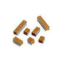
CAP CER 68UF 25V STACKED SMD
Manufacturer
AVX Corporation
Series
TurboCap™r
Specifications of ST203C686MAJ03
Capacitance
68µF
Tolerance
±20%
Temperature Coefficient
X7R
Voltage - Rated
25V
Mounting Type
Surface Mount, MLCC
Operating Temperature
-55°C ~ 125°C
Features
Stacked
Applications
Filtering Switch Mode Power Supplies
Package / Case
6-Stacked SMD, J-Lead
Size / Dimension
0.325" L x 0.300" W (8.26mm x 7.62mm)
Thickness
5.59mm Max
Lead Style
J-Lead
Voltage Rating
25 Volts
Operating Temperature Range
- 55 C to + 125 C
Product
General Type MLCCs
Dielectric Characteristic
X7R
Capacitance Tolerance
± 20%
Capacitor Case Style
DIP
No. Of Pins
6
Capacitor Mounting
SMD
Rohs Compliant
No
Termination Style
Radial
Lead Spacing
6.35 mm
Dimensions
7.62 mm W x 8.26 mm L x 5.59 mm H
Dissipation Factor Df
2.5
Lead Free Status / RoHS Status
Contains lead / RoHS non-compliant
Ratings
-
Lead Spacing
-
Lead Free Status / RoHS Status
Contains lead / RoHS non-compliant
Other names
478-6117


SMPS Capacitors
Application Information on SupraCap
SUPRACAP
High speed switch mode power supplies require extremely
low equivalent series resistance (ESR) and equivalent series
inductance (ESL) capacitors for input and output filtering.
These requirements are beyond the practical limits of
electrolytic capacitors, both aluminum and tantalums, but
are readily met by multilayer ceramic (MLCs) capacitors
(Figure 1).
Theoretical SMPS’s output filter capacitor values are in the
range of 6-10 μF/amp at 40KHz and drop to less than
1 μF/amp at 1MHz. Most electrolytic applications use 10 to
100 times the theoretical value in order to obtain lower ESR
from paralleling many capacitors. This is not necessary with
SupraCap
in the range of milliohms. These extremely low values of
ESR mean low ripple voltage and less self-heating of
the capacitor.
ESR Comparison of Different Capacitor Technologies
1.E+00
1.E-01
1.E-02
1.E-03
®
1.E+03
MLC capacitors which inherently have ESRs
®
- LARGE CAPACITANCE VALUE MLCs
1.E+04
ESR -vs- Frequency
100μF Filter Capacitors
Aluminum Electrolytic 100μF / 50V
Low ESR Solid Tantalum 100μF / 10V
Solid Aluminum Electrolytic 100μF / 16V
MLCC 100μF / 50V
Figure 1
Frequency (Hz)
1.E+05
1.E+06
1.E+07
Output noise spikes are reduced by lowering the filter capac-
itance self-inductance. The ripple current is a triangle wave
form with constant di/dt except when it changes polarity,
then the di/dt is very high. The noise voltage generated by
the filter capacitor is
V
AVX SupraCap
Figure 2 compares a 5.6 μF MLC to a 5.6 μF tantalum which
was specially designed for low ESR and ESL. When subjected
to a di/dt of 200 mA/ns the tantalum shows an ESR of 165
mΩ and an ESL of 18nH versus the MLC’s 4 mΩ and 0.3 nH.
These performance differences allow considerable reduction
in size and weight of the filter capacitor.
Additionally, MLCs are compatible with surface mount
technology reflow and assembly techniques which is the
desirable assembly for conversion frequencies exceeding
1 MHz. Electrolytic capacitors (both aluminum and tantalum)
are not compatible with normal vapor phase (VPS) or infrared
(IR) reflow temperatures (205-215°C) due to electrolyte and
structural problems. AVX SupraCap
with lead frames for either thru-hole or surface mount
assembly. The lead frames act as stress relief for differences
in coefficients of expansion between the large ceramic chip
( 10 ppm/°C) and the PC boards.
Noise
®
= L
Capacitor
DSW 16
CSW 1
di/dt
®
devices have inductance value less than 3nH.
V=2.0mV
50mV
Ta
50mV
MLC
Figure 2
50nS
®
devices are supplied
TPOS-7
T=25.5nS
50nS
VZR-0.2
7
Related parts for ST203C686MAJ03
Image
Part Number
Description
Manufacturer
Datasheet
Request
R

Part Number:
Description:
Inverter Grade Thyristors
Manufacturer:
International Rectifier Corp.
Datasheet:

Part Number:
Description:
Manufacturer:
AVX Corporation
Datasheet:
Part Number:
Description:
Manufacturer:
AVX Corporation
Datasheet:
Part Number:
Description:
Manufacturer:
AVX Corporation
Datasheet:
Part Number:
Description:
Manufacturer:
AVX Corporation
Datasheet: