ADIS16355/PCBZ Analog Devices Inc, ADIS16355/PCBZ Datasheet
ADIS16355/PCBZ
Manufacturer Part Number
ADIS16355/PCBZ
Description
BOARD EVAL FOR ADIS16355
Manufacturer
Analog Devices Inc
Series
iMEMS®, iSensor™r
Datasheets
1.ADIS16350PCBZ.pdf
(24 pages)
2.ADIS16350PCBZ.pdf
(2 pages)
3.ADIS16355PCBZ.pdf
(2 pages)
Specifications of ADIS16355/PCBZ
Sensor Type
Accelerometer, Gyroscope, 3 Axis
Sensing Range
±10g, ±75°/sec, ±150°/sec, ±300°/sec
Interface
SPI Serial
Sensitivity
2.522mg/LSB, 0.018°/sec/LSB
Voltage - Supply
4.75 V ~ 5.25 V
Embedded
No
Utilized Ic / Part
ADIS16355
For Use With
ADISUSBZ - KIT EVAL ADIS W/SOFTWARE USB
Lead Free Status / RoHS Status
Lead free / RoHS Compliant


Preliminary Technical Data
GENERAL DESCRIPTION
The ADIS1635x/PCB is an evaluation board that provides
convenient access to the ADIS1635x using standard 2mm, 2x6,
connectors, which can be accessed using a variety of simple
cabling options. The ADIS1635x/PCB enables quick
integration into an existing digital platform (MCU, DSP, FPGA,
PLD, etc). Four mounting holes (sized for 2-56 or 2mm screws)
have been provided to secure the board during evaluation.
The ADIS1635x has dedicated data/control registers which are
used to control all input/output activity. These registers can be
accessed using the 4-wire serial port interface (SPI) signals on
J1: SCLK, CS, DOUT and DIN. For specific information on
using the ADIS1635x’s SPI interface, refer to the ADIS16350
datasheet. Auxiliary functions, such as the 12-bit ADC input,
12-bit DAC output and digital I/O functions, can be accessed
using J2. C1 and C2 are not installed but the pads are offered
for additional filtering of power supply inputs.
Rev. PrC
Information furnished by Analog Devices is believed to be accurate and reliable.
However, no responsibility is assumed by Analog Devices for its use, nor for any
infringements of patents or other rights of third parties that may result from its use.
Specifications subject to change without notice. No license is granted by implication
or otherwise under any patent or patent rights of Analog Devices. Trademarks and
registered trademarks are the property of their respective owners.
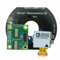
Figure 1 – Basic ADIS1635x/PCB Assembly View
Programmable, Triple Axis Gyro &
Accelerometer Evaluation Board
Ref Des.
J1,J2
J3
C1, C2
SPECIAL NOTES ON HANDLING
Note that the ADIS1635x/PCB is not reverse polarity protected.
Reversing the power supply or applying inappropriate voltages
to any pin (outside the Absolute Maximum Ratings in the
ADIS16350 data sheet) may damage the ADIS1635x.
ORDERING GUIDE
Model
ADIS16350/PCBZ
ADIS16354/PCBZ
ADIS16355/PCBZ
One Technology Way, P.O. Box 9106, Norwood, MA 02062-9106, U.S.A.
Tel: 781.329.4700
Fax: 781.326.8703
Part Description
Mating connector: 3M P/N 152212-0100-GB
Samtec P/N CLM- CLM-112-02-L-D-A
Not installed
Hirose P/N A3-12PA-2SV(71)
Table 1 – ADIS1635x/PCB Parts List
© 2008 Analog Devices, Inc. All rights reserved.
Package Description
Evaluation Board, RoHS Compliant
Evaluation Board, RoHS Compliant
Evaluation Board, RoHS Compliant
ADIS1635x/PCB
www.analog.com
Related parts for ADIS16355/PCBZ
Image
Part Number
Description
Manufacturer
Datasheet
Request
R

Part Number:
Description:
PC EVALUATION SYSTEM
Manufacturer:
Analog Devices Inc
Datasheet:

Part Number:
Description:
±1.7g Dual-Axis IMEMS Accelerometer Evaluation Board
Manufacturer:
Analog Devices Inc
Datasheet:
Part Number:
Description:
Inertial Sensor Evaluation System
Manufacturer:
Analog Devices Inc
Datasheet:
Part Number:
Description:
Manufacturer:
Analog Devices Inc
Datasheet:
Part Number:
Description:
Manufacturer:
Analog Devices Inc
Datasheet:
Part Number:
Description:
Manufacturer:
Analog Devices Inc
Datasheet:
Part Number:
Description:
Manufacturer:
Analog Devices Inc
Datasheet:
Part Number:
Description:
Manufacturer:
Analog Devices Inc
Datasheet:
Part Number:
Description:
Manufacturer:
Analog Devices Inc
Datasheet:
Part Number:
Description:
Manufacturer:
Analog Devices Inc
Datasheet:
Part Number:
Description:
Manufacturer:
Analog Devices Inc
Datasheet:
Part Number:
Description:
Manufacturer:
Analog Devices Inc
Datasheet:
Part Number:
Description:
Manufacturer:
Analog Devices Inc
Datasheet:
ADIS16355/PCBZ Summary of contents
Page 1
... Absolute Maximum Ratings in the ADIS16350 data sheet) may damage the ADIS1635x. ORDERING GUIDE Model ADIS16350/PCBZ ADIS16354/PCBZ ADIS16355/PCBZ Figure 1 – Basic ADIS1635x/PCB Assembly View One Technology Way, P.O. Box 9106, Norwood, MA 02062-9106, U.S.A. Tel: 781.329.4700 Fax: 781.326.8703 ADIS1635x/PCB Table 1 – ...
Page 2
ADIS1635x/PCB Figure 2 – Package drawing Figure 3 - Schematic Rev. PrC | Page Preliminary Technical Data EB07181-0-2/08(PrC) ...