695D106X0050H2T Vishay, 695D106X0050H2T Datasheet
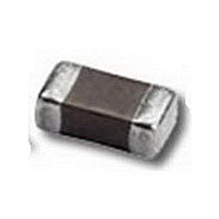
CAPACITOR TANT 10UF, 50V, 1OHM, SMD

695D106X0050H2T

Manufacturer Part Number
695D106X0050H2T
Description
CAPACITOR TANT 10UF, 50V, 1OHM, SMD
Manufacturer
Vishay
Series
695Dr

Specifications of 695D106X0050H2T

Esr
1Ohm
Capacitance
10uF
Tolerance (+ Or -)
20%
Voltage
50VDC
Mounting Style
Surface Mount
Polarity
Polar
Construction
SMT Chip
Case Style
Conformal Coated
Case Code
H
Lead Spacing (nom)
Not Requiredmm
Df
6%
Dcl
5uA
Seal
Not Required
Insulation
Not Required
Failure Rate
Not Required
Wire Form
Not Required
Product Length (mm)
7.7mm
Product Height (mm)
2.79mm
Product Depth (mm)
3.81mm
Product Diameter (mm)
Not Requiredmm
Seated Plane Height
Not Requiredmm
Length W/weld (max)
Not Requiredmm
Operating Temp Range
-55C to 125C
Capacitance Tolerance
± 20%
Voltage Rating
50VDC
No. Of Pins
2
Operating Temperature Range
-55°C To +85°C
Capacitor Mounting
SMD
Termination Type
SMD
Working Voltage, Dc
50V
Rohs Compliant
Yes
Tolerance
20 %
Dimensions
3.81 mm W x 7.7 mm L
Height
2.79 mm
Mfr Case Code
H Case
Product
Tantalum Solid Standard Grade - Other Various
Dissipation Factor Df
6
Leakage Current
5 uAmps
Ripple Current
0.39 mAmps
Termination Style
SMD/SMT
Lead Free Status / RoHS Status
Compliant
Lead Free Status / RoHS Status
Lead free / RoHS Compliant, Compliant

Available stocks

Company
Part Number
Manufacturer
Quantity
Price
Company:
Part Number:
695D106X0050H2T
Quantity:
297
PERFORMANCE CHARACTERISTICS
www.vishay.com/doc?40088
Operating Temperature: - 55 °C to + 85 °C
(to + 125 °C with voltage derating)
Notes
• Preferred tolerance and reel sizes are in bold
• We reserve the right to supply higher voltage ratings and tighter capacitance tolerance capacitors in the same case size.
• Voltage substitutions will be marked with the higher voltage rating.
Note
• The anode termination (D less B) will be a minimum of 0.25 mm (0.010").
* Pb containing terminations are not RoHS compliant, exemptions may apply
Document Number: 40038
Revision: 13-Apr-11
THE PRODUCTS DESCRIBED HEREIN AND THIS DOCUMENT ARE SUBJECT TO SPECIFIC DISCLAIMERS, SET FORTH AT
CASE CODE
695D
TYPE
ORDERING INFORMATION
DIMENSIONS in inches [millimeters]
B
D
G
H
A
E
F
picofarads. The first
This is expressed in
number of zeros to
significant figures.
two digits are the
CAPACITANCE
The third is the
follow.
475
L (MAX.)
0.134
0.185
0.185
0.236
0.236
0.300
0.303
[3.4]
[4.7]
[4.7]
[6.0]
[6.0]
[7.6]
[7.7]
MAX.
L
REF.
D
CAPACITANCE
TOLERANCE
X0 = ± 20 %
X9 = ± 10 %
T
Solid Tantalum Chip Capacitors,
D (REF.)
ANTAMOUNT
0.100
0.150
0.140
0.200
0.220
0.260
0.265
[2.54]
[3.81]
[3.56]
[5.08]
[5.59]
[6.60]
[6.73]
X0
For technical questions, contact:
A
B
This document is subject to change without notice.
To complete the three-digit
point is indicated by an “R”
This is expressed in volts.
block, zeros precede the
voltage rating. A decimal
DC VOLTAGE RATING
0.050 ± 0.015
0.050 ± 0.015
0.095 ± 0.015
0.095 ± 0.015
0.135 ± 0.015
0.100 ± 0.015
0.150 ± 0.015
[1.27 ± 0.38]
[1.27 ± 0.38]
[2.41 ± 0.38]
[2.41 ± 0.38]
[3.43 ± 0.38]
[2.54 ± 0.38]
[3.81 ± 0.38]
(6R3 = 6.3 V).
AT + 85 °C
W
®
004
, Conformal Coated
W
FEATURES
• Pad
• 8 mm, 12 mm 16 mm tape to EIA-481 and
• Mounting: Surface mount
• Terminations: 100 % tin (2) standard, tin/lead
• Compliant to RoHS Directive 2002/95/EC
Capacitance Range: 1.0 μF to 270 μF
Capacitance Tolerance: ± 10 %, ± 20 % standard
Voltage Rating: 4 WV
0.050 ± 0.015
0.050 ± 0.015
0.050 ± 0.015
0.050 ± 0.015
0.070 ± 0.015
0.100 ± 0.015
0.110 ± 0.015
[1.27 ± 0.38]
[1.27 ± 0.38]
[1.27 ± 0.38]
[1.27 ± 0.38]
[1.78 ± 0.38]
[2.54 ± 0.38]
[2.79 ± 0.38]
tantalum@vishay.com
MIL-PRF-55365/4 (CWR06)
reeling per IEC 286-3. 7" [178 mm] standard
13" [330 mm] available
available
CASE CODE
H
See Ratings
Codes table
and Case
compatible
A
MAX.
J
0.023 ± 0.010
[0.584 ± 0.25]
0.040 ± 0.015
0.040 ± 0.015
0.040 ± 0.015
0.040 ± 0.015
0.040 ± 0.015
0.050 ± 0.015
[1.02 ± 0.38]
[1.02 ± 0.38]
[1.02 ± 0.38]
[1.02 ± 0.38]
[1.02 ± 0.38]
[1.27 ± 0.38]
8 = Solder plated
H
4 = Gold plated
TERMINATION
2 = 100 % tin
Special order
A
DC
(60/40)
MAX.
to 50 WV
with
Tantalum Wire
Nib Identifies
Anode (+)
Terminal
J
2
0.067 ± 0.015
0.120 ± 0.015
0.110 ± 0.020
0.170 ± 0.020
0.185 ± 0.020
0.220 ± 0.020
0.220 ± 0.020
[1.70 ± 0.38]
[3.05 ± 0.38]
[2.79 ± 0.51]
[4.32 ± 0.51]
[4.70 ± 0.51]
[5.59 ± 0.51]
[5.59 ± 0.51]
www.vishay.com/doc?91000
194D
DC
Vishay Sprague
B
W = 13" [330 mm] reel
T = Tape and reel
7" [178 mm] reel
See tape and reel
REEL SIZE AND
specifications
PACKAGING
and
www.vishay.com
T
J (MAX.)
695D
0.004
0.004
0.004
0.004
0.004
0.004
0.004
[0.10]
[0.10]
[0.10]
[0.10]
[0.10]
[0.10]
[0.10]
1

Related parts for 695D106X0050H2T

695D106X0050H2T Summary of contents

Page 1

... This document is subject to change without notice. 695D Vishay Sprague with 194D and TERMINATION REEL SIZE AND ...

Page 2

... Vishay Sprague RATINGS AND CASE CODES μ 0.10 0.15 0.22 0.33 0.47 0.68 1.0 1.5 2.2 3 100 F G 120 G G 150 G H 180 H H 220 H H 270 H STANDARD RATINGS CAPACITANCE CASE CODE (μF) 4 100 F 120 G 150 ...

Page 3

... This document is subject to change without notice. 695D Vishay Sprague MAX. DF MAX. ESR MAX. RIPPLE ° °C 100 kHz 120 Hz 100 kHz I RMS (%) () (A) 6 11.000 0. ...

Page 4

... Vishay Sprague STANDARD RATINGS CAPACITANCE CASE CODE (μF) 1.0 A 1.5 B 2.2 B 3.3 D 4 0.47 A 0.68 A 1.0 B 1.5 D 2.2 D 3.3 D 4 0.22 A 0.33 A 0.47 B 0.68 B 1.0 D 1.5 D 2.2 E 3.3 F 4 Notes (1) Tolerance. For 10 % tolerance, specify “X9”; for 20 % tolerance, change to “X0” ...

Page 5

... This document is subject to change without notice. 695D Vishay Sprague MAX. DF MAX. ESR MAX. RIPPLE ° °C 100 kHz 120 Hz 100 kHz I RMS (%) () (A) 4 32.000 0. ...

Page 6

... Vishay Sprague TYPICAL CURVES °C, IMPEDANCE AND ESR VS. FREQUENCY “A CASE” 10 000 1000 µ 0. 100 µ 3 100 1K 10K FREQUENCY IN Hz “D CASE” 1000 100 µ µ 0.1 100 1K 10K FREQUENCY IN Hz “F CASE” 100 10 1 0.1 µ ...

Page 7

... MAXIMUM PERMISSIBLE POWER DISSIPATION °C (W) IN FREE AIR UNITS PER REEL 7" REEL 2500 2500 2500 2500 1000 1500 600 tantalum@vishay.com This document is subject to change without notice. 695D Vishay Sprague 0.060 0.075 0.085 0.095 0.110 0.120 0.150 13" REEL 10 000 10 000 10 000 10 000 ...

Page 8

... Vishay product could result in personal injury or death. Customers using or selling Vishay products not expressly indicated for use in such applications their own risk and agree to fully indemnify and hold Vishay and its distributors harmless from and against any and all claims, liabilities, expenses and damages arising or resulting in connection with such use or sale, including attorneys fees, even if such claim alleges that Vishay or its distributor was negligent regarding the design or manufacture of the part ...

Related keywords