595D156X96R3A2T Vishay, 595D156X96R3A2T Datasheet - Page 9
595D156X96R3A2T
Manufacturer Part Number
595D156X96R3A2T
Description
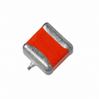
CAP TANT 15UF 6.3V 10% SMD
Manufacturer
Vishay
Series
TANTAMOUNT® 595Dr
Type
Conformal Coatedr
Datasheet
1.595D107X96R3C2T.pdf
(13 pages)
Specifications of 595D156X96R3A2T
Capacitance
15µF
Voltage - Rated
6.3V
Tolerance
±10%
Esr (equivalent Series Resistance)
1.700 Ohm
Operating Temperature
-55°C ~ 125°C
Mounting Type
Surface Mount
Package / Case
1507 (3718 Metric)
Size / Dimension
0.146" L x 0.071" W (3.70mm x 1.80mm)
Height
0.055" (1.40mm)
Manufacturer Size Code
A
Features
General Purpose
Voltage Rating, Dc
6.3V
Capacitor Dielectric Type
TANTALUM ELECTROLYTIC
Tolerance,
10%
Tolerance, -
10%
Temp, Op. Min
-55(DEGREE C)
Temp,
ROHS COMPLIANT
Voltage Rating
6.3 Volts
Esr
1.7 Ohms
Operating Temperature Range
- 55 C to + 85 C
Dimensions
1.8 mm W x 3.7 mm L
Mfr Case Code
A Case
Product
Tantalum Solid Standard Grade - Other Various
Dissipation Factor Df
6
Leakage Current
0.9 uAmps
Termination Style
SMD/SMT
Lead Free Status / RoHS Status
Lead free / RoHS Compliant
Lead Spacing
-
Lead Free Status / Rohs Status
Details


www.vishay.com
9
595D
Vishay Sprague
PERFORMANCE CHARACTERISTICS
8.
8.1
9.
9.1
10.
10.1
11.
12.
12.1
13.
14.
15.
16.
17.
ESR
ESR (Equivalent Series Resistance) shall not
exceed the values listed in the Ratings Table.
Measurement shall be made by the bridge method at
a frequency of 100 kHz and a temperature of + 25 °C.
Life Test: Capacitors shall withstand rated DC
voltage applied at + 85 °C for 2000 hours or derated
DC voltage applied at + 125 °C for 1000 hours.
Following the life test, the dissipation factor and
leakage current shall meet the initial requirement; the
capacitance change shall not exceed ± 10 % of the
initial value; the leakage current shall not exceed
125% of the initial requirement.
Humidity Test: Capacitors shall withstand 1000
hours at + 40 °C, 90 % to 95 % relative humidity, with
no voltage applied.
Following the Humidity Test, capacitance change
shall not exceed ± 10 % of the initial value, dissipation
factor shall not exceed 150 % of the initial
requirement at + 25 °C.
Solderability: Capacitors will meet the solderability
requirements of ANSI/J-STD-002, Test B, Category
3.
Resistance to Soldering Heat: Capacitors mounted
on a substrate will withstand + 260 °C for 5 seconds.
Following the resistance to soldering heat test,
capacitance, dissipation factor and DC leakage
current shall meet the initial requirement.
The small body area of these capacitors does not
allow elaborate marking schemes. All required
information is present on the carton or package in
which the parts are shipped; in addition, part number,
quantity and date code are indicated on the reels.
Terminal Strength: per IEC-384-3, minimum of 5N
shear force.
Enviromental: Mercury, CFC and ODS materials are
not used in the manufacture of these capacitors.
Flammability: Encapsulent materials meet UL94 V0.
Capacitor Failure Mode: The predominant failure
mode for solid tantalum capacitors is increased
leackage current resulting in a shorted circuit.
Capacitor failure may result from excess forward or
reverse DC voltage, surge current, ripple current,
thermal shock or excessive temperature.
The increase in leakage current is caused by a
breakdown in the Ta
information on leakage failure of solid tantalum
capacitors, refer to Vishay Sprague technical paper:
“Leakage Failure Mode in Solid Tantalum Chip
Capacitors.”
2
O
5
dielectric. For additional
For technical questions, contact: tantalum@vishay.com
TANTAMOUNT® Conformal Coated,
Solid Tantalum Chip Capacitors
(Continued)
Maximum CV
GUIDE TO APPLICATION
1.
Standard Conditions, for example; output filters
Severe Conditions, for example; input filters
*For typical wireless applications, Vishay offers 6.3 V Rated
Voltage capacitors with 4.5 V Operation Voltage capability.
Part number indicator is a “W” in place of “R” within the DC
Voltage Rating Identifier.
Example: 595D477X_6W3D2T
Contact factory for availability.
2.
3.
Capacitor Voltage Rating (V)
Capacitor Voltage Rating (V)
Recommended rated working voltage guidelines:
(- 55 °C to + 85 °C)
A-C Ripple Current: The maximum allowable ripple
current shall be determined from the formula:
where,
P =
R
A-C Ripple Voltage: The maximum allowable ripple
voltage shall be determined from the formula:
or, from the formula:
where,
P =
R
Z =
ESR
ESR
=
=
6.3*
6.3*
I
4.0
4.0
10
16
20
25
35
50
10
16
20
25
35
50
rms
V
V
rms
rms
Power Dissipation in Watts at + 25 °C as
given in the table in Paragraph Number 6
(Power Dissipation)
The capacitor Equivalent Series
Resistance at the specified frequency.
Power Dissipation in Watts at + 25 °C as
given in the table in Paragraph Number 6
(Power Dissipation).
The capacitor Equivalent Series
Resistance at the specified frequency.
The capacitor impedance at the specified
frequency.
=
=
=
Z
--------------- -
R
I
rms
ESR
P
--------------- -
R
ESR
×
P
Z
Operating Voltage (V)
Operating Voltage (V)
Document Number: 40007
Revision: 16-Dec-05
2.5
3.6
6.0
2.5
3.3
5.0
8.0
10
12
15
24
28
10
12
15
24
Related parts for 595D156X96R3A2T
Image
Part Number
Description
Manufacturer
Datasheet
Request
R

Part Number:
Description:
357-036-542-201 CARDEDGE 36POS DL .156 BLK LOPRO
Manufacturer:
Vishay
Datasheet:
Part Number:
Description:
357-036-542-201 CARDEDGE 36POS DL .156 BLK LOPRO
Manufacturer:
Vishay
Datasheet:
Part Number:
Description:
357-036-542-201 CARDEDGE 36POS DL .156 BLK LOPRO
Manufacturer:
Vishay
Datasheet:
Part Number:
Description:
357-036-542-201 CARDEDGE 36POS DL .156 BLK LOPRO
Manufacturer:
Vishay
Datasheet:
Part Number:
Description:
357-036-542-201 CARDEDGE 36POS DL .156 BLK LOPRO
Manufacturer:
Vishay
Datasheet:
Part Number:
Description:
357-036-542-201 CARDEDGE 36POS DL .156 BLK LOPRO
Manufacturer:
Vishay
Datasheet:
Part Number:
Description:
357-036-542-201 CARDEDGE 36POS DL .156 BLK LOPRO
Manufacturer:
Vishay
Datasheet:
Part Number:
Description:
357-036-542-201 CARDEDGE 36POS DL .156 BLK LOPRO
Manufacturer:
Vishay
Datasheet:
Part Number:
Description:
357-036-542-201 CARDEDGE 36POS DL .156 BLK LOPRO
Manufacturer:
Vishay
Datasheet:
Part Number:
Description:
357-036-542-201 CARDEDGE 36POS DL .156 BLK LOPRO
Manufacturer:
Vishay
Datasheet:
Part Number:
Description:
357-036-542-201 CARDEDGE 36POS DL .156 BLK LOPRO
Manufacturer:
Vishay
Datasheet:
Part Number:
Description:
357-036-542-201 CARDEDGE 36POS DL .156 BLK LOPRO
Manufacturer:
Vishay
Datasheet:
Part Number:
Description:
357-036-542-201 CARDEDGE 36POS DL .156 BLK LOPRO
Manufacturer:
Vishay
Datasheet:
Part Number:
Description:
357-036-542-201 CARDEDGE 36POS DL .156 BLK LOPRO
Manufacturer:
Vishay
Datasheet:
Part Number:
Description:
357-036-542-201 CARDEDGE 36POS DL .156 BLK LOPRO
Manufacturer:
Vishay
Datasheet: