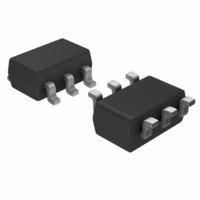
ESDA6V1SC6 STMicroelectronics, ESDA6V1SC6 Datasheet - Page 4

ESDA6V1SC6
Manufacturer Part Number
ESDA6V1SC6
Description
TRANSIL ARRAY QUAD ESD SOT23-6
Manufacturer
STMicroelectronics
Series
TRANSIL™r
Datasheet
1.ESDA5V3SC6.pdf
(11 pages)
Specifications of ESDA6V1SC6
Voltage - Reverse Standoff (typ)
5.25V
Voltage - Breakdown
6.1V
Power (watts)
400W
Polarization
4 Channel Array - Unidirectional
Mounting Type
Surface Mount
Package / Case
SOT-23-6
Polarity
Bidirectional
Channels
4 Channels
Operating Voltage
5.25 V
Breakdown Voltage
6.1 V
Termination Style
SMD/SMT
Peak Pulse Power Dissipation
300 W
Capacitance
140 pF
Maximum Operating Temperature
+ 125 C
Minimum Operating Temperature
- 40 C
Dimensions
1.75 mm W x 3.05 mm L x 1.45 mm H
Lead Free Status / RoHS Status
Lead free / RoHS Compliant
Other names
497-6637-2
ESDA6V1SC6
ESDA6V1SC6
Available stocks
Company
Part Number
Manufacturer
Quantity
Price
Company:
Part Number:
ESDA6V1SC6
Manufacturer:
ST
Quantity:
5 321
Part Number:
ESDA6V1SC6
Manufacturer:
ST
Quantity:
20 000
Company:
Part Number:
ESDA6V1SC6Y
Manufacturer:
INFINEON
Quantity:
13 000
Part Number:
ESDA6V1SC6Y
Manufacturer:
ST
Quantity:
20 000
Application information
2
2.1
2.2
4/11
Figure 7.
500
100
10
1
25
I [T ] / I [T =25°C]
R
j
R
Application information
Calculation of the clamping voltage use of the dynamic
resistance
The ESDA family has been designed to clamp fast spikes like ESD. Generally the PCB
designers need to calculate easily the clamping voltage V
dynamic resistance in addition to the classical parameters. The voltage across the
protection cell can be calculated with the following formula:
Where I
As the value of the dynamic resistance remains stable for a surge duration lower than 20 µs,
the 2.5 µs rectangular surge is well adapted. In addition both rise and fall times are
optimized to avoid any parasitic phenomenon during the measurement of R
Dynamic resistance measurement
The short duration of the ESD has led us to prefer a more adapted test wave, as below
defined, to the classical 8/20µs and 10/1000 µs surges.
Figure 9.
Relative variation of leakage
current versus junction
temperature (typical values)
j
50
PP
is the peak current through the ESDA cell.
T (°C)
2.5 µs duration measurement wave
j
75
ESDA14V2SC5/SC6
ESDA6V1SC5/SC6
&
ESDA5V3SC5/SC6
100
ESDA17SC6
ESDA19SC6
I
Ipp
&
ESDA25SC6
125
V
CL
Figure 8.
tp = 2.5µs
= V
2µs
5.00
1.00
0.10
0.01
BR
0.5
I
FM
ESDA14V2SC5/SC6
ESDA6V1SC5/SC6
+ R
(A)
ESDA5V3SC5/SC6
&
d
1.0
I
Peak forward voltage drop versus
peak forward current
(typical values)
PP
1.5
CL
. This is why we give the
ESDA19SC6
2.0
V
FM
t
(V)
2.5
ESDA25SC6
3.0
d
.
ESDAxxSCx
T = 25°C
j
3.5
ESDA17SC6
4.0


