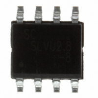
SLVU2.8-8.TBT Semtech, SLVU2.8-8.TBT Datasheet - Page 4

SLVU2.8-8.TBT
Manufacturer Part Number
SLVU2.8-8.TBT
Description
IC TVS ARRAY 8-LINE 2.8V 8SOIC
Manufacturer
Semtech
Datasheet
1.SLVU2.8-8.TBT.pdf
(9 pages)
Specifications of SLVU2.8-8.TBT
Voltage - Reverse Standoff (typ)
2.8V
Voltage - Breakdown
3V
Power (watts)
600W
Polarization
4 Channel Array - Bidirectional
Mounting Type
Surface Mount
Package / Case
8-SOIC
Diode Type
ESD Protection
Clamping Voltage Vc Max
17V
Operating Voltage
2.8V
Diode Case Style
SOIC
No. Of Pins
8
Breakdown Voltage Min
3V
Capacitance, Cd
8pF
Junction Capacitance
8pF
Rohs Compliant
Yes
Leaded Process Compatible
Yes
Lead Free Status / RoHS Status
Lead free / RoHS Compliant
Other names
SLVU2.8-8TR
Available stocks
Company
Part Number
Manufacturer
Quantity
Price
Company:
Part Number:
SLVU2.8-8.TBT
Manufacturer:
Semtech
Quantity:
135
Part Number:
SLVU2.8-8.TBT
Manufacturer:
SEMTECH/美国升特
Quantity:
20 000
Device Connection for Protection of Eight Data Lines
Electronic equipment is susceptible to transient distur-
bances from a variety of sources including: ESD to an
open connector or interface, direct or nearby lightning
strikes to cables and wires, and charged cables “hot
plugged” into I/O ports. The SLVU2.8-8 is designed to
protect sensitive components from damage and latch-
up which may result from such transient events. The
SLVU2.8-8 can be configured to protect four high-
speed line pairs differentially, or four lines to ground
(common mode). The device is connected as follows:
1 . Differential Protection of four line pairs:
Circuit Board Layout Recommendations for Suppres-
sion of ESD.
Good circuit board layout is critical for the suppression
of ESD induced transients. The following guidelines are
recommended:
PROTECTION PRODUCTS
Applications Information
2008 Semtech Corp.
Line pairs are connected at pins 1 and 2, 3 and 4,
5 and 6, and 7 and 8.
Place the device near the input terminals or con-
nectors to restrict transient coupling.
Minimize the path length between the TVS and the
protected line.
Minimize all conductive loops including power and
ground loops.
The ESD transient return path to ground should be
kept as short as possible.
Never run critical signals near board edges.
Use ground planes whenever possible.
4
Differential Protection of Four Line Pairs
1
2
3
4
SLVU2.8-8 Circuit Diagram
From Connector
SLVU2.8-8
www.semtech.com
8
7
6
5


