BZW04P37-E3/54 Vishay, BZW04P37-E3/54 Datasheet

TVS 400W 37V 7% UNIDIR DO-204AL

BZW04P37-E3/54

Manufacturer Part Number
BZW04P37-E3/54
Description
TVS 400W 37V 7% UNIDIR DO-204AL
Manufacturer
Vishay
Series
TransZorb®r
Datasheet

Specifications of BZW04P37-E3/54

Voltage - Reverse Standoff (typ)
36.8V
Voltage - Breakdown
40.9V
Power (watts)
400W
Polarization
Unidirectional
Mounting Type
Through Hole
Package / Case
DO-204AL, DO-41, Axial
Lead Free Status / RoHS Status
Lead free / RoHS Compliant
DEVICES FOR BI-DIRECTION APPLICATIONS
For
BZW04P-6V4B).
Electrical characteristics apply in both directions.
Notes:
(1) Non-repetitive current pulse, per Fig. 3 and derated above T
(2) Measured on 8.3 ms single half sine-wave or equivalent square wave, duty cycle = 4 pulses per minute maximum
(3) V
Document Number: 88316
Revision: 22-Oct-08
PRIMARY CHARACTERISTICS
MAXIMUM RATINGS AND THERMAL CHARACTERISTICS (T
PARAMETER
Peak pulse power dissipation with a 10/1000 µs waveform
Peak pulse current with a 10/1000 µs waveform
Power dissipation on infinite heatsink at T
Peak forward surge current, 8.3 ms single half sine-wave uni-directional only
Maximum instantaneous forward voltage at 25 A for uni-directional only
Operating junction and storage temperature range
I
FSM
F
= 3.5 V for BZW04P(-)188 and below; V
bi-directional
(uni-directional only)
T
P
J
V
P
PPM
max.
WM
D
T
DO-204AL (DO-41)
RANS
types,
PDD-Americas@vishay.com, PDD-Asia@vishay.com, PDD-Europe@vishay.com
For technical questions within your region, please contact one of the following:
Z
use
ORB
5.8 V to 376 V
L
= 75 °C (Fig. 5)
B
F
175 °C
400 W
1.5 W
®
40 A
= 5.0 V for BZW04P(-)213 and above
(1)
suffix
Transient Voltage Suppressors
(1)
(e.g.
(Fig. 1)
A
= 25 °C per Fig. 2
(3)
FEATURES
TYPICAL APPLICATIONS
Use in sensitive electronics protection against voltage
transients induced by inductive load switching and
lighting on ICs, MOSFET, signal lines of sensor
units
telecommunication.
MECHANICAL DATA
Case: DO-204AL, molded epoxy over passivated chip
Molding compound meets UL 94 V-0 flammability
rating
Base P/N-E3 - RoHS compliant, commercial grade
Base P/NHE3 - RoHS compliant, high reliability/
automotive grade (AEC Q101 qualified)
Terminals: Matte tin plated leads, solderable per
J-STD-002 and JESD22-B102
E3 suffix meets JESD 201 class 1A whisker test, HE3
suffix meets JESD 201 class 2 whisker test
Note: BZW04-213(B) ~ BZW04-376(B) for commercial grade only
Polarity: For uni-directional types the color band
denotes cathode end, no marking on bi-directional
types
• Glass passivated chip junction
• Available in uni-directional and bi-directional
• 400 W peak pulse power capability with a
• Excellent clamping capability
• Very fast response time
• Low incremental surge resistance
• Solder dip 260 °C, 40 s
• Component in accordance to RoHS 2002/95/EC
(2)
BZW04P-5V8 thru BZW04-376
10/1000 µs waveform, repetitive rate (duty
cycle): 0.01 %
and WEEE 2002/96/EC
for
Vishay General Semiconductor
SYMBOL
T
J
P
I
I
consumer,
, T
PPM
FSM
A
P
V
PPM
D
F
STG
= 25 °C unless otherwise noted)
See next table
- 55 to + 175
computer,
3.5/5.0
LIMIT
400
1.5
40
industrial
www.vishay.com
UNIT
°C
W
W
A
A
V
and
1

Related parts for BZW04P37-E3/54

BZW04P37-E3/54 Summary of contents

Page 1

... V = 3.5 V for BZW04P(-)188 and below Document Number: 88316 For technical questions within your region, please contact one of the following: Revision: 22-Oct-08 PDD-Americas@vishay.com, PDD-Asia@vishay.com, PDD-Europe@vishay.com BZW04P-5V8 thru BZW04-376 ® Transient Voltage Suppressors FEATURES • Glass passivated chip junction • Available in uni-directional and bi-directional • ...

Page 2

... BZW04P23B BZW04-23 BZW04-23B BZW04P26 BZW04P26B BZW04-26 BZW04-26B BZW04P28 BZW04P28B BZW04-28 BZW04-28B BZW04P31 BZW04P31B BZW04-31 BZW04-31B BZW04P33 BZW04P33B BZW04-33 BZW04-33B BZW04P37 BZW04P37B BZW04-37 BZW04-37B BZW04P40 BZW04P40B BZW04-40 BZW04-40B BZW04P44 BZW04P44B BZW04-44 BZW04-44B BZW04P48 BZW04P48B BZW04-48 BZW04-48B BZW04P53 BZW04P53B BZW04-53 BZW04-53B BZW04P58 BZW04P58B ...

Page 3

... BZW04-273B BZW04P299 BZW04P299B BZW04-299 BZW04-299B BZW04P342 BZW04P342B BZW04-342 BZW04-342B BZW04P376 BZW04P376B BZW04-376 BZW04-376B Notes: ≤ (1) Pulse test (2) Surge current waveform per Fig. 3 and derated per Fig. 2 (3) All terms and symbols are consistent with ANSI/IEEE C62.35 (4) For bi-directional types having and less, the I ...

Page 4

... BZW04P-5V8 thru BZW04-376 Vishay General Semiconductor RATINGS AND CHARACTERISTICS CURVES ( °C unless otherwise noted) A 100 Non-Repetitive Pulse Waveform shown in Fig ° 0.1 0 100 t - Pulse Width (µs) d Figure 1. Peak Pulse Power Rating Curve 100 100 125 T - Initial Temperature (°C) J Figure 2. Pulse Power or Current vs. Initial Junction Temperature ...

Page 5

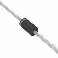
... PACKAGE OUTLINE DIMENSIONS in inches (millimeters) Document Number: 88316 For technical questions within your region, please contact one of the following: Revision: 22-Oct-08 PDD-Americas@vishay.com, PDD-Asia@vishay.com, PDD-Europe@vishay.com BZW04P-5V8 thru BZW04-376 Vishay General Semiconductor DO-204AL (DO-41) 1.0 (25.4) MIN. 0.107 (2.7) 0.080 (2.0) DIA. 0.205 (5.2) ...

Page 6

... Vishay product could result in personal injury or death. Customers using or selling Vishay products not expressly indicated for use in such applications their own risk and agree to fully indemnify and hold Vishay and its distributors harmless from and against any and all claims, liabilities, expenses and damages arising or resulting in connection with such use or sale, including attorneys fees, even if such claim alleges that Vishay or its distributor was negligent regarding the design or manufacture of the part ...

Related keywords