P4KE400CA-E3/54 Vishay, P4KE400CA-E3/54 Datasheet - Page 3
P4KE400CA-E3/54
Manufacturer Part Number
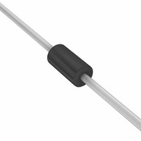
P4KE400CA-E3/54
Description
TVS 400W 400V 5% BIDIR AXIAL
Manufacturer
Vishay
Series
TransZorb®r
Datasheet
1.P4KE100-E354.pdf
(6 pages)
Specifications of P4KE400CA-E3/54
Voltage - Reverse Standoff (typ)
342V
Voltage - Breakdown
380V
Power (watts)
400W
Polarization
Bidirectional
Mounting Type
Through Hole
Package / Case
DO-204AL, DO-41, Axial
Polarity
Bidirectional
Clamping Voltage
548 V
Operating Voltage
342 V
Breakdown Voltage
380 V
Peak Surge Current
0.73 A
Peak Pulse Power Dissipation
400 W
Maximum Operating Temperature
175 C
Minimum Operating Temperature
- 55 C
Dimensions
2.7 (Max) mm W x 5.2 (Max) mm L
Lead Free Status / RoHS Status
Lead free / RoHS Compliant


Notes:
(1) Pulse test: t
(2) Surge current waveform per Fig. 3 and derated per Fig. 2
(3) For bi-directional types having V
(4) All terms and symbols are consistent with ANSI/IEEE C62.35
Document Number: 88365
Revision: 22-Oct-08
ELECTRICAL CHARACTERISTICS (T
DEVICE TYPE
P4KE82
P4KE82A
P4KE91
P4KE91A
P4KE100
P4KE100A
P4KE110
P4KE110A
P4KE120
P4KE120A
P4KE130
P4KE130A
P4KE150
P4KE150A
P4KE160
P4KE160A
P4KE170
P4KE170A
P4KE180
P4KE180A
P4KE200
P4KE200A
P4KE220
P4KE220A
P4KE250
P4KE250A
P4KE300
P4KE300A
P4KE350
P4KE350A
P4KE400
P4KE400A
P4KE440
P4KE440A
P4KE480
P4KE480A
P4KE510
P4KE510A
P4KE540
P4KE540A
THERMAL CHARACTERISTICS (T
PARAMETER
Typical thermal resistance, junction to lead
Typical thermal resistance, junction to ambient, L
p
≤ 50 ms
BREAKDOWN VOLTAGE
MIN.
73.8
77.9
81.9
86.5
90.0
95.0
99.0
105
108
114
117
124
135
143
144
152
153
162
162
171
180
190
198
209
225
237
270
285
315
333
360
380
396
418
432
456
459
485
486
513
V
BR
PDD-Americas@vishay.com, PDD-Asia@vishay.com, PDD-Europe@vishay.com
For technical questions within your region, please contact one of the following:
(V)
AT I
WM
T
(1)
MAX.
of 10 V and less, the I
90.2
86.1
95.5
100
110
105
121
116
132
126
143
137
165
158
176
168
187
179
198
189
220
210
242
231
275
263
330
315
385
368
440
420
484
462
528
504
561
535
594
567
Lead
CURRENT
A
I
T
TEST
= 25 °C unless otherwise noted)
1.0
1.0
1.0
1.0
1.0
1.0
1.0
1.0
1.0
1.0
1.0
1.0
1.0
1.0
1.0
1.0
1.0
1.0
1.0
1.0
1.0
1.0
1.0
1.0
1.0
1.0
1.0
1.0
1.0
1.0
1.0
1.0
1.0
1.0
1.0
1.0
1.0
1.0
1.0
1.0
(mA)
= 10 mm
A
= 25 °C unless otherwise noted)
D
limit is doubled
VOLTAGE
V
STAND-
WM
OFF
66.4
70.1
73.7
77.8
81.0
85.5
89.2
94.0
97.2
102
105
111
121
128
130
136
138
145
146
154
162
171
175
185
202
214
243
256
284
300
324
342
356
376
389
408
413
434
437
459
(V)
MAXIMUM
REVERSE
LEAKAGE
I
D
AT V
(3)
1.0
1.0
1.0
1.0
1.0
1.0
1.0
1.0
1.0
1.0
1.0
1.0
1.0
1.0
1.0
1.0
1.0
1.0
1.0
1.0
1.0
1.0
1.0
1.0
1.0
1.0
1.0
1.0
1.0
1.0
1.0
1.0
1.0
1.0
1.0
1.0
1.0
1.0
1.0
1.0
SYMBOL
(µA)
WM
R
R
Vishay General Semiconductor
θJL
θJA
P4KE6.8 thru P4KE540A
MAXIMUM
CURRENT
I
PPM
PULSE
PEAK
0.93
0.79
0.83
0.70
0.73
0.63
0.66
0.58
0.61
0.55
0.57
0.52
0.54
3.4
3.5
3.1
3.2
2.8
2.9
2.5
2.6
2.3
2.4
2.1
2.2
1.9
1.9
1.7
1.8
1.6
1.7
1.6
1.6
1.4
1.5
1.2
1.2
1.1
1.2
1.0
(2)
(A)
LIMIT
100
66
CLAMPING
MAXIMUM
VOLTAGE
AT I
V
C
118
113
131
125
144
137
158
152
173
165
187
179
215
207
230
219
244
234
258
246
287
274
344
328
360
344
430
414
504
482
574
548
631
602
686
658
729
698
772
740
PPM
(V)
TEMPERATURE
COEFFICIENT
www.vishay.com
MAXIMUM
OF V
°C/W
°C/W
UNIT
(%/°C)
0.105
0.105
0.106
0.106
0.106
0.106
0.107
0.107
0.107
0.107
0.107
0.107
0.108
0.108
0.108
0.108
0.108
0.108
0.108
0.108
0.108
0.108
0.108
0.108
0.110
0.110
0.110
0.110
0.110
0.110
0.110
0.110
0.110
0.110
0.110
0.110
0.110
0.110
0.110
0.110
BR
3
Related parts for P4KE400CA-E3/54
Image
Part Number
Description
Manufacturer
Datasheet
Request
R

Part Number:
Description:
TVS 400W 400V 5% BIDIR AXIAL
Manufacturer:
Vishay
Datasheet:

Part Number:
Description:
TVS Diodes - Transient Voltage Suppressors 400W 400V Bidirect
Manufacturer:
Vishay
Datasheet:

Part Number:
Description:
TVS Diodes - Transient Voltage Suppressors 400W 400V 5% Bidir
Manufacturer:
Vishay
Datasheet:
Part Number:
Description:
TVS Diodes - Transient Voltage Suppressors 400W 400V Bidirect
Manufacturer:
Vishay
Datasheet:
Part Number:
Description:
TVS Diodes - Transient Voltage Suppressors 400W 400V Bidirect
Manufacturer:
Vishay
Datasheet:
Part Number:
Description:
TVS Diodes - Transient Voltage Suppressors 400W 400V Bidirect
Manufacturer:
Vishay
Datasheet:
Part Number:
Description:
TVS 400W 400V 10% BIDIR AXIAL
Manufacturer:
Vishay
Datasheet:
Part Number:
Description:
357-036-542-201 CARDEDGE 36POS DL .156 BLK LOPRO
Manufacturer:
Vishay
Datasheet:
Part Number:
Description:
357-036-542-201 CARDEDGE 36POS DL .156 BLK LOPRO
Manufacturer:
Vishay
Datasheet:
Part Number:
Description:
357-036-542-201 CARDEDGE 36POS DL .156 BLK LOPRO
Manufacturer:
Vishay
Datasheet:
Part Number:
Description:
357-036-542-201 CARDEDGE 36POS DL .156 BLK LOPRO
Manufacturer:
Vishay
Datasheet:
Part Number:
Description:
357-036-542-201 CARDEDGE 36POS DL .156 BLK LOPRO
Manufacturer:
Vishay
Datasheet: