LCE22-E3/54 Vishay, LCE22-E3/54 Datasheet - Page 2
LCE22-E3/54
Manufacturer Part Number
LCE22-E3/54
Description
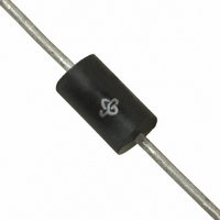
TVS UNIDIR 1.5KW 22V 10% 1.5KE
Manufacturer
Vishay
Series
TransZorb®r
Specifications of LCE22-E3/54
Voltage - Reverse Standoff (typ)
22V
Voltage - Breakdown
24.4V
Power (watts)
1500W
Polarization
Unidirectional
Mounting Type
Through Hole
Package / Case
1.5KE, Axial
Polarity
Unidirectional
Clamping Voltage
39.4 V
Operating Voltage
22 V
Breakdown Voltage
24.4 V
Peak Surge Current
38 A
Peak Pulse Power Dissipation
1500 W
Maximum Operating Temperature
175 C
Minimum Operating Temperature
- 65 C
Dimensions
5.3 (Max) mm W x 9.5 (Max) mm L
Lead Free Status / RoHS Status
Lead free / RoHS Compliant
Lead Free Status / RoHS Status
Lead free / RoHS Compliant, Lead free / RoHS Compliant


LCE6.5 thru LCE28A
Vishay General Semiconductor
Note:
(1) All the above devices are UL listed for Telecom application protection 497B, file number E136766
www.vishay.com
2
ELECTRICAL CHARACTERISTICS (T
PART
NUMBER
LCE6.5
LCE6.5A
LCE7.0
LCE7.0A
LCE7.5
LCE7.5A
LCE8.0
LCE8.0A
LCE8.5
LCE8.5A
LCE9.0
LCE9.0A
LCE10
LCE10A
LCE11
LCE11A
LCE12
LCE12A
LCE13
LCE13A
LCE14
LCE14A
LCE15
LCE15A
LCE16
LCE16A
LCE17
LCE17A
LCE18
LCE18A
LCE20
LCE20A
LCE22
LCE22A
LCE24
LCE24A
LCE26
LCE26A
LCE28
LCE28A
VOLTAGE
STAND-
V
OFF
6.5
6.5
7.0
7.0
7.5
7.5
8.0
8.0
8.5
8.5
9.0
9.0
(V)
10
10
11
11
12
12
13
13
14
14
15
15
16
16
17
17
18
18
20
20
22
22
24
24
26
26
28
28
WM
BREAKDOWN
7.22
7.22
7.78
7.78
8.33
8.33
8.89
8.89
9.44
9.44
10.0
10.0
11.1
11.1
12.2
12.2
13.3
13.3
14.4
14.4
15.6
15.6
16.7
16.7
17.8
17.8
18.9
18.9
20.0
20.0
22.2
22.2
24.4
24.4
26.7
26.7
28.9
28.9
31.1
31.1
MIN.
VOLTAGE
V
(V)
PDD-Americas@vishay.com, PDD-Asia@vishay.com, PDD-Europe@vishay.com
BR
For technical questions within your region, please contact one of the following:
MAX.
8.82
7.98
9.51
8.60
10.2
9.21
10.9
9.83
11.5
10.4
12.2
11.1
13.6
12.3
14.9
13.5
16.3
14.7
17.6
15.9
19.1
17.2
20.4
18.5
21.8
19.7
23.1
20.9
24.4
22.1
27.1
24.5
29.8
26.9
32.6
29.5
35.3
31.9
38.0
34.4
CURRENT
TEST
AT I
10.0
10.0
10.0
10.0
10.0
10.0
mA
1.0
1.0
1.0
1.0
1.0
1.0
1.0
1.0
1.0
1.0
1.0
1.0
1.0
1.0
1.0
1.0
1.0
1.0
1.0
1.0
1.0
1.0
1.0
1.0
1.0
1.0
1.0
1.0
1.0
1.0
1.0
1.0
1.0
1.0
T
MAXIMUM
REVERSE
LEAKAGE
I
D
1000
1000
50.0
50.0
10.0
10.0
V
500
500
250
250
100
100
5.0
5.0
5.0
5.0
5.0
5.0
5.0
5.0
5.0
5.0
5.0
5.0
5.0
5.0
5.0
5.0
5.0
5.0
5.0
5.0
5.0
5.0
5.0
5.0
5.0
5.0
5.0
5.0
AT
(µA)
A
WM
= 25 °C unless otherwise noted)
CLAMPING
MAXIMUM
VOLTAGE
V
AT I
12.3
11.2
13.3
12.0
14.3
12.9
15.0
13.6
15.9
14.4
16.9
15.4
18.8
17.0
20.1
18.2
22.0
19.9
23.8
21.5
25.8
23.2
26.9
24.4
28.8
26.0
30.5
27.6
32.2
29.2
35.8
32.4
39.4
35.5
43.0
38.9
46.6
42.1
50.1
45.5
C
(V)
PP
MAXIMUM
CURRENT
PULSE
(FIG 3)
PEAK
I
100
100
100
100
100
100
100
100
100
PPM
(A)
94
89
97
80
88
74
82
68
75
63
70
58
65
56
61
52
57
49
54
46
51
42
46
38
42
35
39
32
36
30
33
CAPACITANCE
JUNCTION
MAXIMUM
AT 0 (V)
(pF)
100
100
100
100
100
100
100
100
100
100
100
100
100
100
100
100
100
100
100
100
100
100
100
100
100
100
100
100
100
100
100
100
100
100
100
100
100
100
100
100
BLOCKING
WORKING
VOLTAGE
INVERSE
V
(V)
75
75
75
75
75
75
75
75
75
75
75
75
75
75
75
75
75
75
75
75
75
75
75
75
75
75
75
75
75
75
75
75
75
75
75
75
75
75
75
75
WIB
Document Number: 88357
BLOCKING
MAXIMUM
LEAKAGE
CURRENT
INVERSE
AT V
I
D
1.0
1.0
1.0
1.0
1.0
1.0
1.0
1.0
1.0
1.0
1.0
1.0
1.0
1.0
1.0
1.0
1.0
1.0
1.0
1.0
1.0
1.0
1.0
1.0
1.0
1.0
1.0
1.0
1.0
1.0
1.0
1.0
1.0
1.0
1.0
1.0
1.0
1.0
1.0
1.0
(mA)
Revision: 20-Oct-08
WIB
BLOCKING
MINIMUM
VOLTAGE
INVERSE
PEAK
V
100
100
100
100
100
100
100
100
100
100
100
100
100
100
100
100
100
100
100
100
100
100
100
100
100
100
100
100
100
100
100
100
100
100
100
100
100
100
100
100
(V)
PIB
Related parts for LCE22-E3/54
Image
Part Number
Description
Manufacturer
Datasheet
Request
R

Part Number:
Description:
TVS UNIDIR 1.5KW 22V 10% 1.5KE
Manufacturer:
Vishay
Datasheet:

Part Number:
Description:
TVS Diodes - Transient Voltage Suppressors 1500W 22V Low Cap
Manufacturer:
Vishay
Datasheet:
Part Number:
Description:
TVS Diodes - Transient Voltage Suppressors 1500W 22V Low Cap
Manufacturer:
Vishay

Part Number:
Description:
TVS Diodes - Transient Voltage Suppressors 1500W 22V Low Cap
Manufacturer:
Vishay Semiconductors
Datasheet:
Part Number:
Description:
TVS Diodes - Transient Voltage Suppressors 1500W 22V Low Cap
Manufacturer:
Vishay Semiconductors
Datasheet:

Part Number:
Description:
357-036-542-201 CARDEDGE 36POS DL .156 BLK LOPRO
Manufacturer:
Vishay
Datasheet:
Part Number:
Description:
357-036-542-201 CARDEDGE 36POS DL .156 BLK LOPRO
Manufacturer:
Vishay
Datasheet:
Part Number:
Description:
357-036-542-201 CARDEDGE 36POS DL .156 BLK LOPRO
Manufacturer:
Vishay
Datasheet:
Part Number:
Description:
357-036-542-201 CARDEDGE 36POS DL .156 BLK LOPRO
Manufacturer:
Vishay
Datasheet:
Part Number:
Description:
357-036-542-201 CARDEDGE 36POS DL .156 BLK LOPRO
Manufacturer:
Vishay
Datasheet:
Part Number:
Description:
357-036-542-201 CARDEDGE 36POS DL .156 BLK LOPRO
Manufacturer:
Vishay
Datasheet:
Part Number:
Description:
357-036-542-201 CARDEDGE 36POS DL .156 BLK LOPRO
Manufacturer:
Vishay
Datasheet:
Part Number:
Description:
357-036-542-201 CARDEDGE 36POS DL .156 BLK LOPRO
Manufacturer:
Vishay
Datasheet:
Part Number:
Description:
357-036-542-201 CARDEDGE 36POS DL .156 BLK LOPRO
Manufacturer:
Vishay
Datasheet:
Part Number:
Description:
357-036-542-201 CARDEDGE 36POS DL .156 BLK LOPRO
Manufacturer:
Vishay
Datasheet: