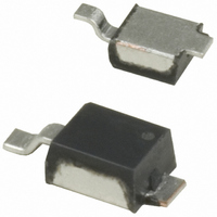
UPTB17E3 Microsemi Commercial Components Group, UPTB17E3 Datasheet - Page 2

UPTB17E3
Manufacturer Part Number
UPTB17E3
Description
TVS BIDIRECT 1000W 17V POWRMITE1
Manufacturer
Microsemi Commercial Components Group
Datasheet
1.UPT15RE3.pdf
(3 pages)
Specifications of UPTB17E3
Voltage - Reverse Standoff (typ)
17V
Voltage - Breakdown
19V
Power (watts)
1000W
Polarization
Bidirectional
Mounting Type
Surface Mount
Package / Case
Powermite®
Lead Free Status / RoHS Status
Lead free / RoHS Compliant
Other names
UPTB17E3CT
Copyright © 2007
10-15-2007 REV H
ELECTRICAL CHARACTERISTICS @ 25
UPT10 & UPT10R
UPT15 & UPT15R
UPT17 & UPT17R
UPT24 & UPT24R
Symbol
UPT12 &UPT12R
UPT28 &UPT28R
UPT33 &UPT33R
UPT48 &UPT48R
* See Figure 1 for I
UPT8 & UPT8R
Unidirectional
V
V
Pulse Waveform for Exponential Surge
P
I
(BR)
I
C
PP
WM
PP
D
UPT5R
UPT5
(add e3 suffix)
DEVICE TYPE
8700 E. Thomas Rd. PO Box 1390, Scottsdale, AZ 85252 USA, (480) 941-6300, Fax: (480) 947-1503
Breakdown Voltage: The minimum voltage the device will exhibit at a specified current.
Working Peak Standoff Voltage: The maximum peak voltage that can be applied over the operating
temperature range.
Peak Pulse Power: The peak power that can be applied for a specified pulse width and waveform.
Standby Current: The maximum current that will flow at the specified voltage and temperature.
Peak Pulse Current: The peak current that can be applied for a specified pulse width and waveform.
Capacitance: The capacitance in picofarads of the TVS as defined @ 0 volts at a frequency of 1 MHz.
tp: Pulse time duration is defined as
decays to 50% of I
(Rise time to 100% of I
that point where the pulse current
t – TIME – (μs)
FIGURE 1
S C O T T S D A L E D I V I S I O N
Bi-directional
PP
UPTB10
UPTB12
UPTB15
UPTB17
UPTB24
UPTB28
UPTB33
UPTB48
UPTB8
waveform of 8/20
PP
.
PP
= 8μs.)
STANDOFF
VOLTAGE
RATED
V
10
12
15
17
24
28
33
48
V
5
5
8
WM
SYMBOLS & DEFINITIONS
µs
OUTLINE AND CIRCUIT
Scottsdale Division
Microsemi
BREAKDOWN
o
V
C
VOLTAGE
(BR)
MINIMUM
11.0
13.8
16.7
19.0
28.4
31.0
36.8
54.0
6.0
6.0
9.0
@ 1 mA
V
Definition
SURFACE MOUNT TRANSIENT
MAXIMUM
CURRENT
STANDBY
I
Peak Pulse Power vs. Pulse Duration
D
VOLTAGE SUPPRESSORS
@ V
μA
50
5
2
2
1
1
1
1
1
1
1
UPT5Re3 – UPT48Re3
UPTB8e3 – UPTB48e3
WM
UPT5e3 – UPT48e3
tp – PULSE TIME
CURRENT*
MAXIMUM
FIGURE 2
PULSE
PEAK
89.4
62.1
47.2
40.3
33.9
30.8
22.0
19.2
16.4
11.2
60
I
A
PP
EXPONENTIAL PULSE
(Pulse time duration is defined as
that point where the pulse current
decays to 50% of I
CLAMPING
V
MAXIMUM
VOLTAGE
C
13.7
18.0
21.6
26.0
29.2
43.2
47.8
56.7
84.3
@ 10A*
9.5
9.5
V
PP
.)
COEFFICIENT
MAXIMUM
of V
TEMP.
α
%/
.030
.030
.040
.045
.050
.055
.060
.070
.075
.080
.090
V(BR)
Page 2
o
(BR)
C


