TAJE337M004RNJ AVX Corporation, TAJE337M004RNJ Datasheet - Page 17
TAJE337M004RNJ
Manufacturer Part Number
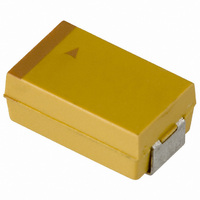
TAJE337M004RNJ
Description
CAPACITOR TANT 330UF 4V 20% SMD
Manufacturer
AVX Corporation
Series
TAJr
Type
Moldedr
Specifications of TAJE337M004RNJ
Capacitance
330µF
Voltage - Rated
4V
Tolerance
±20%
Operating Temperature
-55°C ~ 125°C
Mounting Type
Surface Mount
Package / Case
2917 (7343 Metric)
Size / Dimension
0.287" L x 0.169" W (7.30mm x 4.30mm)
Height
0.161" (4.10mm)
Manufacturer Size Code
E
Features
General Purpose
Lead Free Status / RoHS Status
Lead free / RoHS Compliant
Lead Spacing
-
Esr (equivalent Series Resistance)
-
Lead Free Status / RoHS Status
Compliant, Lead free / RoHS Compliant
Other names
TAJE337M004R
TAJE337M004R
TAJE337M004R


Technical Summary and
Application Guidelines
Operating Temperature.
If the operating temperature is below the rated temperature
for the capacitor then the operating reliability will be
improved as shown in Figure 3. This graph gives a correction
factor FT for any temperature of operation.
Circuit Impedance.
All solid tantalum capacitors require current limiting
resistance to protect the dielectric from surges. A series
resistor is recommended for this purpose. A lower circuit
impedance may cause an increase in failure rate, especially
at temperatures higher than 20°C. An inductive low imped-
ance circuit may apply voltage surges to the capacitor and
similarly a non-inductive circuit may apply current surges to
the capacitor, causing localized over-heating and failure. The
recommended impedance is 1
feasible, equivalent voltage derating should be used
(See MIL HANDBOOK 217E). The graph, Figure 4, shows
the correction factor, FR, for increasing series resistance.
For circuit impedances below 0.1 ohms per volt, or for any
mission critical application, circuit protection should be con-
sidered. An ideal solution would be to employ an AVX SMT
thin-film fuse in series.
Figure 4. Correction factor to failure rate F for series resistance
Figure 3: Correction factor to failure rate F for ambient
100.0
R on basic failure rate FB for a typical component
10.0
0.10
0.01
1.0
20
temperature T for typical component
30
Circuit resistance
ohms/volt
40
2.0
1.0
0.8
0.6
0.4
0.2
0.1
3.0
50
(60% con. level).
(60% con. level).
60
Temperature
70
80
per volt. Where this is not
0.07
0.1
0.2
0.3
0.4
0.6
0.8
1.0
FR
90
100 110 120
Example calculation
Consider a 12 volt power line. The designer needs about
10µF of capacitance to act as a decoupling capacitor near a
video bandwidth amplifier. Thus the circuit impedance will be
limited only by the output impedance of the board’s power
unit and the track resistance. Let us assume it to be about
2 Ohms minimum, i.e. 0.167 Ohms/Volt. The operating
temperature range is -25°C to +85°C. If a 10µF 16 Volt
capacitor was designed in the operating failure rate would
be as follows.
Thus
If the capacitor was changed for a 20 volt capacitor, the
operating failure rate will change as shown.
3.2 Dynamic.
As stated in Section 1.2.4, the solid Tantalum capacitor has
a limited ability to withstand voltage and current surges.
Such current surges can cause a capacitor to fail. The
expected failure rate cannot be calculated by a simple
formula as in the case of steady-state reliability. The two
parameters under the control of the circuit design engineer
known to reduce the incidence of failures are derating and
series resistance.
The table below summarizes the results of trials carried out
at AVX with a piece of equipment which has very low series
resistance with no voltage derating applied. That is the
capacitor was tested at its rated voltage.
Results of production scale derating experiment
As can clearly be seen from the results of this experiment,
the more derating applied by the user, the less likely the
probability of a surge failure occurring.
It must be remembered that these results were derived from
a highly accelerated surge test machine, and failure rates in
the low ppm are more likely with the end customer.
A commonly held misconception is that the leakage current
of a Tantalum capacitor can predict the number of failures
which will be seen on a surge screen. This can be disproved
by the results of an experiment carried out at AVX on 47µF
10V surface mount capacitors with different leakage
currents. The results are summarized in the table on the fol-
lowing page.
Capacitance
and Voltage
100µF 10V
47µF 16V
22µF 25V
a) FT = 1.0 @ 85°C
b) FR = 0.85 @ 0.167 Ohms/Volt
c) FU = 0.08 @ applied voltage/rated
d) FB = 1%/1000 hours, basic failure rate level
F = 1.0 x 0.85 x 0.08 x 1 = 0.068%/1000 Hours
FU = 0.018 @ applied voltage/rated voltage = 60%
F = 1.0 x 0.85 x 0.018 x 1 = 0.0153%/1000 Hours
units tested
Number of
1,547,587
2,256,258
voltage = 75%
632,876
50% derating
applied
0.03%
0.01%
0.05%
No derating
applied
1.1%
0.5%
0.3%
45
Related parts for TAJE337M004RNJ
Image
Part Number
Description
Manufacturer
Datasheet
Request
R

Part Number:
Description:
Manufacturer:
AVX Corporation
Datasheet:
Part Number:
Description:
Manufacturer:
AVX Corporation
Datasheet:
Part Number:
Description:
Manufacturer:
AVX Corporation
Datasheet:
Part Number:
Description:
Manufacturer:
AVX Corporation
Datasheet:
Part Number:
Description:
Manufacturer:
AVX Corporation
Datasheet: