GTC030-18-10S Amphenol Industrial Operations, GTC030-18-10S Datasheet - Page 7
GTC030-18-10S
Manufacturer Part Number
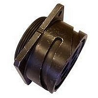
GTC030-18-10S
Description
CONN RCPT 4POS PANEL MNT W/SCKT
Manufacturer
Amphenol Industrial Operations
Series
GT, MIL-5015 Derivativer
Datasheet
1.GT18TF.pdf
(95 pages)
Specifications of GTC030-18-10S
Connector Type
Receptacle, Female Sockets
Mounting Type
Panel Mount, Flange; Through Hole
Number Of Positions
4
Termination
Crimp
Orientation
N (Normal)
Fastening Type
Reverse Bayonet Lock
Shell Material, Finish
Olive Drab, Silver Plated
Shell Size - Insert
18-10
Ingress Protection
IP67 - Dust Tight, Waterproof
Connector Body Material
Aluminum
Gender
Receptacle
Contact Gender
Socket
Connector Mounting
Panel
Connector Shell Size
18
Insert Arrangement
18-10
Lead Free Status / RoHS Status
Lead free by exemption / RoHS compliant by exemption
Features
-
Shell Size, Military
-
Lead Free Status / RoHS Status
Lead free by exemption / RoHS compliant by exemption


GT Series
insert alternate positioning
To avoid cross-plugging problems in applications requir-
ing the use of more than one connector of the same size
and arrangement, alternate rotations are available as
indicated in the accompanying charts.
As shown in the diagram below, the front face of the pin
insert is rotated within the shell in a clockwise direction
from the normal shell key. The socket insert would be
rotated counter-clockwise the same number of degrees
in respect to the normal shell key.
Arrangement
Position W
10SL-4
14S-2
14S-5
14S-7
14S-9
16-9
16-10
16-11
16-13
16S-1
16S-4
16S-5
16S-6
16S-8
18-1
18-3
18-4
18-8
18-10
18-11
18-12
18-15
18-20
18-22
18-29
20-3
20-4
20-5
20-6
20-15
20-17
20-18
Insert
View looking into front face of pin insert or rear of socket insert.
63
90
70
35
90
35
35
80
35
70
90
70
35
35
70
80
90
70
90
70
45
35
70
80
90
35
W
–
–
–
–
–
–
Position X
120
110
180
145
110
180
110
110
110
145
180
170
145
110
110
120
170
120
180
145
180
145
110
110
145
180
110
X
–
–
–
–
–
Degrees
240
270
215
250
270
250
250
250
215
270
265
215
250
250
240
265
240
270
215
270
215
250
250
215
270
250
Y
–
–
–
–
–
–
Position Y
290
325
325
325
280
325
290
290
325
325
290
280
290
290
325
290
280
325
Z
–
–
–
–
–
–
–
–
–
–
–
–
–
–
Arrangement
20-19
20-21
20-23
20-24
20-27
20-29
20-33
22-1
22-2
22-4
22-5
22-8
22-9
22-10
22-11
22-13
22-20
22-22
22-23
22-27
22-28
24-2
24-9
24-10
24-11
24-22
24-27
24-96
28-2
28-3
28-5
28-6
Insert
Position Z
90
35
35
35
35
80
35
70
35
35
35
70
35
35
35
35
35
80
80
80
35
80
35
45
80
65
35
70
35
70
W
–
–
5
180
110
110
110
110
110
145
110
110
110
145
110
110
110
110
110
110
110
110
110
145
110
145
X
–
–
–
–
–
–
–
–
–
Degrees
The following insert arrangements have the same alter-
nate insert rotations for W, X, Y and Z, which are:
T
16-7
18-5
18-9
18-13
18-14
20-7
20-8
20-9
20-12
20-14
80
W
270
250
250
250
250
250
215
250
250
250
215
250
250
250
250
250
250
250
250
250
250
250
215
250
215
Y
–
–
–
–
–
–
–
20-16
20-20
20-22
22-3
22-6
22-12
22-14
22-15
22-16
22-17
110
325
325
325
325
280
280
325
290
325
325
325
290
325
325
325
325
280
280
280
325
280
325
280
325
290
325
290
X
Z
–
–
–
–
–
Degrees
22-18
22-19
22-21
22-24
22-25
22-29
22-33
22-34
24-1
24-3
*Additional rotations available; consult Amphenol for
information.
250
Arrangement
Y
28-7
28-12
28-18
28-22
28-AY
32-2
32-5
32-7
32-8
32-15
32-17
32-25
32-64*
32-68
32-82
36-3
36-4
36-5
36-6
36-9
36-10
36-14
36-15
36-AF
40-1
40-5
40-9
40-10
40-35
40-56
40-AG
Insert
24-4
24-5
24-6
24-7
24-12
24-14
24-16
24-17
24-20
24-21
280
Z
35
90
70
70
45
70
35
80
80
35
45
60
80
30
30
70
70
35
80
80
90
60
65
65
33
65
65
70
72
37
W
–
24-28
24-AJ
28-1
28-4
28-8
28-9
28-10
28-11
28-14
28-15
110
180
145
145
110
145
110
125
125
110
110
120
100
145
145
120
110
125
125
180
125
130
125
125
130
144
74
X
–
–
–
–
Degrees
28-16
28-17
28-19
28-20
28-21
32-1
32-3
32-4
32-6
32-9
250
270
215
215
250
215
250
235
235
250
250
110
215
215
240
250
235
235
270
245
235
225
225
230
216
285
Y
–
–
–
–
–
32-10
32-12
32-13
32-22
32-AF
36-1
36-7
36-8
36-13
40-53
325
290
290
290
325
280
280
280
250
290
290
325
280
280
305
300
270
310
310
290
288
322
Z
–
–
–
–
–
–
–
–
–
Related parts for GTC030-18-10S
Image
Part Number
Description
Manufacturer
Datasheet
Request
R

Part Number:
Description:
CIRCULAR CONN RCPT SIZE 14S, 3POS, PANEL
Manufacturer:
Amphenol Industrial Operations
Datasheet:
Part Number:
Description:
CIRCULAR CONN RCPT SIZE 18, 10POS, PANEL
Manufacturer:
Amphenol Industrial Operations
Datasheet:
Part Number:
Description:
CIRCULAR CONN RCPT SIZE 18, 10POS, PANEL
Manufacturer:
Amphenol Industrial Operations
Datasheet:
Part Number:
Description:
CIRCULAR CONN RCPT SIZE 18, 10POS, PANEL
Manufacturer:
Amphenol Industrial Operations
Datasheet:
Part Number:
Description:
CIRCULAR CONN RCPT SIZE 18, 10POS, PANEL
Manufacturer:
Amphenol Industrial Operations
Datasheet:

Part Number:
Description:
JAM NUT CONN, RCPT, SIZE 9, 6POS, PANEL
Manufacturer:
Amphenol Industrial Operations
Datasheet:

Part Number:
Description:
PT 41C 41#20 PIN RECP
Manufacturer:
Amphenol Industrial Operations
Part Number:
Description:
PT 41C 41#20 SKT RECP
Manufacturer:
Amphenol Industrial Operations