TB6M Switchcraft Inc., TB6M Datasheet - Page 69
TB6M
Manufacturer Part Number
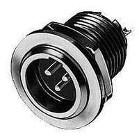
TB6M
Description
CONN RCPT CORD MINI 6POS MALE
Manufacturer
Switchcraft Inc.
Series
Tini Q-G® TBr
Type
Panel Socketr
Specifications of TB6M
Rohs Information
Switchcraft RoHS Info.
Connector Type
Receptacle, Male Pins
Number Of Positions
6
Shell Size - Insert
XLR
Mounting Type
Panel Mount, Bulkhead - Rear Side Nut
Termination
Solder Cup
Fastening Type
Latch Lock
Orientation
Keyed
Shell Material, Finish
Copper, Nickel Plated
Features
Mounting Hardware
Number Of Ports
1Port
Body Orientation
Straight
Number Of Terminals
6
Contact Material
Copper Alloy
Number Of Contacts
6POS
Mounting Style
Panel
Termination Method
Solder
Operating Temp Range
-55C to 85C
Standard
Mini (Tiny) XLR
Gender
Male
Number Of Positions / Contacts
6
Termination Style
Solder
Contact Plating
Silver
Color
Black
Voltage Rating
125 V
Current Rating
1.5 A
Product Type
Connectors
Shell Plating
Nickel
Angle
Straight
Application
Commercial
Brand/series
TB
Contact Type
Pin
Current, Rating
1.5 A
Flammability Rating
UL94-V0
Material, Dielectric
Thermoplastic
Material, Housing
Copper Alloy
Mount Method
Front
Primary Type
XLR
Strain Relief
Internal
Thickness, Panel
0.25 "
Voltage, Rating
125 VAC
Lead Free Status / RoHS Status
Lead free / RoHS Compliant
Ingress Protection
-
Shell Size, Military
-
Lead Free Status / Rohs Status
Lead free / RoHS Compliant


64
w w w . s w i t c h c r a f t . c o m
CONNECTORS & RECEPTACLES
SLIM-LINE CONNECTORS
SLIM-LINE CONNECTORS
SL18 RECEPTACLES
Front of Panel Mount
SL MALE RECEPTACLES
SL FEMALE RECEPTACLES
SLIM-LINE CONNECTORS (continued)
Front of panel mount; 2 through 5 pins (male) or 2 through
5 contacts (female). Also 2-, 3- and 4-contact insert with
3 shunted (N.C.) contacts. Mounting locknut (Part Number
SL01), lockwasher (Part Number SL02), and flat washer
(Part Number SL03) supplied.
Part Number
Part Number
SL182M
SL183M
SL184M
SL185M
SL182F
SL183F
SL184F
SL185F
* Please visit the product pages on our website for the most up-to-date product information
(17.7)
.696
Contacts
PANEL HOLE
Pins
2
3
4
5
2
3
4
5
Arrangements
SL183FS (typical)
Arrangements
DIMENSIONS ARE FOR REFERENCE ONLY
Contact
Pin
1
2
3
4
A
B
C
D
INSTALLING CABLE CLAMP ON INSERT
To install cable clamp on any insert:
1. Position insert approximately as shown in the diagram.
2. Hold clamp at approximately 30° angle (as shown). Place
3. Press center finger forward into slot and reduce angle of
Cable Clamp SL04
tip of clamp center finger into slot under molded ring “A”.
Note position of notch on insert in relation to slot.
clamp until clamp shoulders seat just ahead of molded
barrier on rear of insert “B”.
MOLDED
RING
“A”
INSERT
NOTCH
ON
(mm)
Note: Contact your Switchcraft Representative for price and delivery
Inch
PHONE: 773 792 - 2700
® Registered trademark of Switchcraft, Inc.
INSERT
“B”
CABLE
CLAMP
Related parts for TB6M
Image
Part Number
Description
Manufacturer
Datasheet
Request
R

Part Number:
Description:
CONN PLUG PHONE 1/4" 2POS RED
Manufacturer:
Switchcraft Inc.
Datasheet:

Part Number:
Description:
CONN PLUG 2-COND 1/4" PHONE SLD
Manufacturer:
Switchcraft Inc.
Datasheet:

Part Number:
Description:
CONN PLUG PHONE SILENT 2-COND
Manufacturer:
Switchcraft Inc.
Datasheet:

Part Number:
Description:
THICK PANEL/GOLD PLA
Manufacturer:
Switchcraft Inc.
Datasheet:

Part Number:
Description:
CONN JACK PHONE 1/4" 2POS CLOSED
Manufacturer:
Switchcraft Inc.
Datasheet:

Part Number:
Description:
CONN PHONE JACK 2COND 1/4" OPEN
Manufacturer:
Switchcraft Inc.
Datasheet:
Part Number:
Description:
CONN JACK PHONE 1/4" 2POS W/HDWR
Manufacturer:
Switchcraft Inc.
Datasheet:

Part Number:
Description:
CONN PLUG PHONE .206" 2POS BLACK
Manufacturer:
Switchcraft Inc.
Datasheet:
Part Number:
Description:
CONN PLUG PHONE 1/4" FLAT 2POS
Manufacturer:
Switchcraft Inc.
Datasheet:

Part Number:
Description:
CONN PLUG FLAT PHONE 1/4" 3-COND
Manufacturer:
Switchcraft Inc.
Datasheet:

Part Number:
Description:
PHONE T-JACK PANEL .25" STD SGL
Manufacturer:
Switchcraft Inc.
Datasheet:

Part Number:
Description:
CONN JACK PANEL 96POS W/O JACK
Manufacturer:
Switchcraft Inc.
Datasheet:
Part Number:
Description:
CONN PLUG PHONE .206" 3POS BLACK
Manufacturer:
Switchcraft Inc.
Datasheet:

Part Number:
Description:
CONN JACK 1/4" 3-COND IN-LINE
Manufacturer:
Switchcraft Inc.
Datasheet:

Part Number:
Description:
CONN PLUG AUDIO PHONE 3COND BLK
Manufacturer:
Switchcraft Inc.
Datasheet: