N3433-6002RB 3M, N3433-6002RB Datasheet - Page 3
N3433-6002RB
Manufacturer Part Number
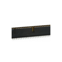
N3433-6002RB
Description
PROTECT HEADER STRGT 50 CONTACT
Manufacturer
3M
Series
3000r
Type
PCB Plugr
Datasheets
1.3403-0001.pdf
(32 pages)
2.N3793-6002RB.pdf
(5 pages)
3.N3429-6602RB.pdf
(4 pages)
4.N3433-6002RB.pdf
(7 pages)
Specifications of N3433-6002RB
Contact Type
Male Pin
Connector Type
Header, Shrouded
Number Of Positions
50
Number Of Positions Loaded
All
Pitch
0.100" (2.54mm)
Number Of Rows
2
Row Spacing
0.100" (2.54mm)
Contact Mating Length
0.240" (6.10mm)
Mounting Type
Through Hole
Termination
Solder
Contact Finish
Gold
Contact Finish Thickness
30µin (0.76µm)
Color
Black
Product Type
Headers - Latch / Eject
Number Of Positions / Contacts
50
Mounting Style
Through Hole
Mounting Angle
Straight
Termination Style
Solder
Housing Material
Polyester, Glass Filled
Contact Material
Copper Alloy
Contact Plating
Gold
Current Rating
1 A
Agency Approvals
cUL, UL
Angle
Straight
Brand/series
3000 Series
Current, Rating
2 A
Flammability Rating
UL94V-0
Height
0.68 in.
Length, Overall
3.265 "
Length, Pin
0.112 "
Length, Tail
5.08 um
Material, Contact
Copper Alloy
Material, Housing
Glass Filled Polyester
Material, Insulation
PBT
Mounting Hole Size
0.1 "
Number Of Contacts
50
Pin Spacing
0.1 "
Primary Type
High Temperature
Resistance, Insulation
> 1 x 10^9 Ohms @ 500 VDC
Special Features
Four-Wall
Temperature, Operating
-55 to +105 °C
Lead Free Status / RoHS Status
Lead free / RoHS Compliant
Features
-
Fastening Type
-
Lead Free Status / Rohs Status
Lead free / RoHS Compliant
Other names
5111165079
51111650790
80400027902
MHS50L
N34336002RB
51111650790
80400027902
MHS50L
N34336002RB


3M
.100” × .100” Latch/Ejector, Straight and Right Angle
3
Electronic Solutions Division
Interconnect Solutions
http://www.3M.com/interconnects/
Ordering Information
Notes: 1. Notches A & C will accomodate 3M Polarizing Keys (3M Part #3518 or #N3518).
2. Mounting hardware: From solder side of pc board use #4-24 thread cutting screw (3M Part # 3341-5) and .116 [2.95] dia mounting hole. For right angle version
3. The recommended PCB hole size for the kinked tail positions on the .112 solder tail connector is .035 ± .002. See page 4 for kink position details (K2 version).
4. Contact your 3M sales representative for custom requirements.
Blank = Std. Temp Gray (PBT) /(Blank or UB Pltg. Req’d.)
N = High Temp Beige (PCT) /(Blank or UB Pltg. Req’d.)
N = High Temp Black (PCT)/(RB Plating Req’d)
Pin Qty
Number Suffix
only, #2-56 bolt and nut (3M Part # 3341-6) with .106 [2.69] dia mounting hole may be used.
10
14
16
20
24
26
30
34
40
50
60
64
3M Part
-5XO3
-6XO3
-5XX2
-6XX2
™
Number
3M Part
Four-Wall Header
3793
3314
3408
3428
3627
3429
3440
3431
3432
3433
3372
3764
(2.39) to .125 (3.18)
Solder Tail for 0.94
“Y”
Thick PC Board
Thick PC Board
Contact Tail
Solder Tail for
.062 (1.57)
3.965 (100.71)
3M Part Number
1.465 (37.21)
1.765 (44.83)
1.965 (49.91)
2.065 (52.45)
2.265 (57.53)
2.465 (62.61)
2.765 (70.23)
3.765 (95.63)
1.565 (39.75)
3.265 (82.93)
.100 ± .003
[2.54]
1.265 (32.13)
[1.52]
(See Table 1)
C L
.060
A
Recommended Mounting Hole Pattern
.300
[7.62]
Side to Side Stackability
5 = Right Angle Solder Tails
.155 ± .010
.112 ± .010
Dim E
(2.84)
(3.94)
6 = Straight Solder Tails
1.104 (28.04)
1.304 (33.12)
1.404 (35.66)
1.604 (40.74)
1.804 (45.82)
1.904 (48.36)
2.104 (53.44)
2.304 (58.52)
2.604 (66.14)
3.104 (78.84)
3.604 (91.54)
3.804 (96.62)
Pin Configuration
B
Table 1
Dimensions
Position 1
.0245 ± .0005
.0245 ± .0005
ø.106
(Straight)
[2.69]
Table 2
.100 ± .003
[2.54]
(0.622)
(0.622)
(See Note 2)
Dim F
[8.94]
.352
B
Dim G
0.865 (21.97)
or
1.065 (27.05)
1.165 (29.59)
1.365 (34.67)
1.565 (39.75)
1.665 (42.29)
1.865 (47.37)
2.065 (52.45)
2.365 (60.07)
2.865 (72.77)
3.365 (85.47)
3.565 (90.55)
X3XXX-XXXXXX
Pin Cross Section
ø.116
Latch/Ejector System
0 = No Latch/Ejector installed
2 = Short Roll Pin Latch/Ejectors
3 = Long Roll Pin Latch/Ejectors
5 = Short, Snap-In Latch/Ejectors
6 = Long, Snap-In Latch/Ejectors
[2.95]
C
.028 ± .001
.028 ± .001
Diagonals
(0.71)
(0.71)
0.705 (17.91)
0.905 (22.99)
1.005 (25.53)
1.205 (30.61)
1.405 (35.69)
1.505 (38.23)
1.705 (43.31)
1.905 (48.39)
2.205 (56.01)
2.705 (68.71)
3.205 (81.41)
3.405 (86.49)
Corner Radii
.0075 Ref
.0075 Ref
D
(0.191)
(0.191)
Polarizing
"Y"
Notches
For technical, sales or ordering information call
ABC
ABC
ABC
ABC
ABC
ABC
ABC
ABC
ABC
ABC
BC
BC
(0.89) (See Note 3)
Tail
02 = for .062 [1.57] thick board
03 = for .094 to .125 [2.39 to 3.18] thick board
K2 = kinked for .062 [1.57] thick board
0.035 ± .003 (0.89)
.100 ± .003
[2.54]
0.035 ± .003
C L
Plating
RB = 30 μ” [ 0.76 μm ] Gold and 200 μ” [ 5.08 μm ] Matte Tin
over 100 μ” [ 2.54 μm ] Nickel (App. E1 & C1 Apply)
Blank or UB = 30 μ” (0.76 μm ] Gold and 200 μ” [ 5.08 μm ]
Tin Lead over 100 μ” [ 2.54 μm ] Nickel (App. E3 & C2 Apply)
[0.74]
.029
Dim G
Recommended Mounting Hole Pattern
.41
[10.4]
Max to Edge of PCB
for Daisy Chain
3M is a trademark of 3M Company.
Inch
Tolerance Unless Noted
(Right Angle)
(See Note 2)
.100 ± .003
[2.54]
Position 1
[ ] Dimensions for
Reference only
ø.106
± .1
[2.69]
.0
[5.89]
.232
C
(mm)
Inch
Dim G
or ø.116
± .01
.00
3000 Series
[2.95]
800-225-5373
± .005
.000
Sheet 3 of 4
TS-0772-G
Related parts for N3433-6002RB
Image
Part Number
Description
Manufacturer
Datasheet
Request
R

Part Number:
Description:
PROTECT HEADER RT ANG 50 CONTACT
Manufacturer:
3M
Datasheet:

Part Number:
Description:
CONN HEADER 50POS STR LONG LATCH
Manufacturer:
3M
Datasheet:

Part Number:
Description:
CONN HEADER 50PS R/A LONG LATCH
Manufacturer:
3M
Datasheet:

Part Number:
Description:
CONN HEADER 50PS R/A SHORT LATCH
Manufacturer:
3M
Datasheet:

Part Number:
Description:
CONN HEADER 50POS STR LONG LATCH
Manufacturer:
3M
Datasheet:

Part Number:
Description:
3M-MINI-CLAMP/PLUG/WMIC/2MM/3POS/TYPE A/ORANGE/3M LOGO
Manufacturer:
3M
Datasheet:
Part Number:
Description:
3M-MINI-CLAMP/PLUG/WMIC/2MM/4POS/TYPE A/YELLOW/3M LOGO
Manufacturer:
3M
Datasheet:
Part Number:
Description:
3M-MINI-CLAMP/PLUG/WMIC/2MM/4POS/TYPE A/ORANGE/3M LOGO
Manufacturer:
3M
Datasheet:
Part Number:
Description:
3M-MINI-CLAMP/SKT PANELMOUNT/WMIC/2MM/3POS/TYPE A/RED/3M LOGO
Manufacturer:
3M
Datasheet:
Part Number:
Description:
3M-MINI-CLAMP/SKT PANELMOUNT/WMIC/2MM/3POS/TYPE A/YELLOW/3M LO
Manufacturer:
3M
Datasheet:
Part Number:
Description:
3M-MINI-CLAMP/SKT/WMIC/2MM/3POS/TYPE A/ORANGE/3M LOGO
Manufacturer:
3M
Datasheet:
Part Number:
Description:
3M-MINI-CLAMP/SKT PANELMOUNT/WMIC/2MM/3POS/TYPE A/ORANGE/3M LO
Manufacturer:
3M
Datasheet:
Part Number:
Description:
3M-MINI-CLAMP/SKT PANELMOUNT/WMIC/2MM/4POS/TYPE A/RED/3M LOGO
Manufacturer:
3M
Datasheet:
Part Number:
Description:
3M-MINI-CLAMP/SKT/WMIC/2MM/4POS/TYPE A/YELLOW/3M LOGO
Manufacturer:
3M
Datasheet:
Part Number:
Description:
3M-MINI-CLAMP/SKT PANELMOUNT/WMIC/2MM/4POS/TYPE A/YELLOW/3M LO
Manufacturer:
3M
Datasheet: