N3428-5002RB 3M, N3428-5002RB Datasheet - Page 3
N3428-5002RB
Manufacturer Part Number
N3428-5002RB
Description
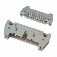
PROTECT HEADER RT ANG 20 CONTACT
Manufacturer
3M
Series
3000r
Type
PCB Plugr
Specifications of N3428-5002RB
Contact Type
Male Pin
Connector Type
Header, Shrouded
Number Of Positions
20
Number Of Positions Loaded
All
Pitch
0.100" (2.54mm)
Number Of Rows
2
Row Spacing
0.100" (2.54mm)
Contact Mating Length
0.240" (6.10mm)
Mounting Type
Through Hole, Right Angle
Termination
Solder
Contact Finish
Gold
Contact Finish Thickness
30µin (0.76µm)
Color
Black
Agency Approvals
cUL, UL
Angle
Right
Brand/series
3000 Series
Contact Plating
Gold
Contact Termination Area Plating
200 u in. 60⁄40 Tin⁄Lead
Current, Rating
2 A
Finish, Housing Test
Tin-Lead
Flammability Rating
UL94V-0
Height
0.68 in.
Length, Overall
1.765 "
Length, Pin
0.112 "
Length, Tail
2.84 mm
Material, Contact
Copper Alloy
Material, Housing
Glass Filled Polyester
Material, Insulation
Glass Filled Polyester (PBT)
Mounting Hole Size
0.1 "
Number Of Contacts
20
Pin Spacing
0.1 "
Primary Type
High Temperature
Resistance, Insulation
>1 x 10^9 Ohms @ 500 VDC
Special Features
Four-Wall
Temperature, Operating
-55 to +105 °C
Product Type
Headers - Latch / Eject
Contact Gender
Pin (Male)
Number Of Positions / Contacts
20
Mounting Style
Through Hole
Termination Style
Solder
Contact Material
Copper Alloy
Voltage Rating
1 KV
Current Rating
2 A
Lead Free Status / RoHS Status
Lead free / RoHS Compliant
Features
-
Fastening Type
-
Lead Free Status / Rohs Status
RoHS Compliant part
Other names
5111165066
51111650660
80400027779
MHR20L
N34285002RB
51111650660
80400027779
MHR20L
N34285002RB


3M
.100″ × .100″ Latch/Ejector, Straight and Right Angle, High Temp Option
3
Interconnect Solutions
http://www.3M.com/interconnects/
Notes:
“Y”
1. Notches A & C will accomodate 3M Polarizing Keys (3M Part #N3518).
2. Accepts Rear and Front mounting hardware:
3. The recommended PCB hole size for the kinked tail positions on the .112 solder tail connector is .035 ± .002.
Rear Entry: #4-24 thread cutting screw, 3M Part #3341-5, .116 [2.95] dia mounting hole
Front Entry: (Prior to installation of latch on Straight Versions) #2-56 bolt and nut, 3M Part #3341-6,
.106 [2.69] dia mounting hole
Refer to TS-0972 for the positions kinked.
.100 ± .003
[2.54]
Quantity
C L
Number Suffix
[1.52]
.060
Pak 100 4-Wall Header
Pin
Pin
10
14
16
20
24
26
30
34
40
50
60
64
3M Part
3M Part
-5XX2
-6XX2
-5X03
-6X03
-5X05
-6X05
Recommended Mounting Hole Pattern
.300
[7.62]
Side to Side Stackability
3M Part
3M Part
Number
3793
3314
3408
3428
3627
3429
3440
3431
3432
3433
3372
3764
Wire Wrap Tail for up to
3 Levels of Wire Wrap
Thick PC Board
Thick PC Board
Solder Tail for
Solder Tail for
C
Contact Tail
.094 [2.39] to
.062 [1.57]
.125 [3.18]
«.106
[2.69]
Position 1
t t T il
.100 ± .003
[2.54]
(Straight)
3.96 [100.7]
1.26 [32.1]
1.46 [37.2]
1.56 [39.7]
1.76 [44.8]
1.96 [49.8]
2.06 [52.4]
2.26 [57.4]
2.46 [62.6]
2.76 [70.2]
3.26 [82.9]
3.76 [95.6]
(See Note 2)
[8.94]
.352
B
A
or
G Dia
«.116
[2.95]
Di
Dimension E
1.105 [28.07]
1.305 [33.15]
1.405 [35.69]
1.605 [40.77]
1.805 [45.85]
1.905 [48.39]
2.105 [53.47]
2.305 [58.55]
2.605 [66.17]
3.105 [78.87]
3.605 [91.57]
3.805 [96.65]
.61 Ref
[2.84]
[3.94]
[15.5]
.112
.155
B
i
Table 1
Dimensions
E
Table 2
0.0245
0.0245
0.0250
Dimension F
1.065 [27.05]
1.165 [29.59]
1.365 [34.67]
1.565 [39.75]
1.665 [42.29]
1.865 [47.37]
2.065 [52.45]
2.365 [60.07]
2.865 [72.77]
3.365 [85.47]
3.565 [90.55]
.865 [21.97]
[0.622]
[0.622]
[0.635]
”Y”
.100 ± .003
[2.54]
±
±
C
±
.0005
.0005
.002
[0.74]
.029
C L
Pin Cross Section
Recommended Mounting Hole Pattern
0.028
0.028
0.035
Diagonals
1.71 43.43]
1.01 [25.6]
1.21 [30.7]
1.41 [35.8]
1.51 [38.3]
1.91 [48.5]
2.21 [56.1]
2.71 [68.8]
3.21 [81.5]
3.41 [86.6]
.41
[10.4]
Max to Edge of PCB
for Daisy Chain
For technical, sales or ordering information call
.71 [18.0]
.91 [23.1]
[0.71]
[0.71]
[0.90]
±
±
±
D
.001
.001
.003
«.106
.100 ± .003
[2.54]
(Right Angle)
[2.69]
3M is a trademark of 3M Company.
Corner Radii
Notches Provided
0.0075 Ref
0.0075 Ref
0.003 Max
(See Note 2)
[0.191]
[0.191]
Position 1
Polarization
Polarization
[0.08]
[5.89]
.232
A B C
A B C
A B C
A B C
A B C
A B C
A B C
A B C
A B C
A B C
or
B C
B C
C
G Dia
Inch
«.116
Tolerance Unless Noted
[2.95]
[ ] Dimensions for
[0.89] (See Note 3)
Reference only
± .1
.0
Di
Dimension G
.035
3000 Series
.035
.045
Inch
[mm]
[0.89]
[1.14]
800-225-5373
±
± .01
.00
±
±
TS-0772-03
Sheet 3 of 4
.003
i
.003
.003
G
± .005
.000
Related parts for N3428-5002RB
Image
Part Number
Description
Manufacturer
Datasheet
Request
R

Part Number:
Description:
CONN HEADER 20PS STR SHORT LATCH
Manufacturer:
3M
Datasheet:

Part Number:
Description:
CONN HEADER 20POS STR LONG LATCH
Manufacturer:
3M
Datasheet:

Part Number:
Description:
PROTECT HEADER STRGT 20 CONTACT
Manufacturer:
3M
Datasheet:

Part Number:
Description:
CONN HEADER 20POS R/A NO LATCH
Manufacturer:
3M
Datasheet:

Part Number:
Description:
CONN HEADER 20PS R/A SHORT LATCH
Manufacturer:
3M
Datasheet:
Part Number:
Description:
3M-MINI-CLAMP/PLUG/WMIC/2MM/3POS/TYPE A/ORANGE/3M LOGO
Manufacturer:
3M
Datasheet:
Part Number:
Description:
3M-MINI-CLAMP/PLUG/WMIC/2MM/4POS/TYPE A/YELLOW/3M LOGO
Manufacturer:
3M
Datasheet:
Part Number:
Description:
3M-MINI-CLAMP/PLUG/WMIC/2MM/4POS/TYPE A/ORANGE/3M LOGO
Manufacturer:
3M
Datasheet:
Part Number:
Description:
3M-MINI-CLAMP/SKT PANELMOUNT/WMIC/2MM/3POS/TYPE A/RED/3M LOGO
Manufacturer:
3M
Datasheet:
Part Number:
Description:
3M-MINI-CLAMP/SKT PANELMOUNT/WMIC/2MM/3POS/TYPE A/YELLOW/3M LO
Manufacturer:
3M
Datasheet:
Part Number:
Description:
3M-MINI-CLAMP/SKT/WMIC/2MM/3POS/TYPE A/ORANGE/3M LOGO
Manufacturer:
3M
Datasheet:
Part Number:
Description:
3M-MINI-CLAMP/SKT PANELMOUNT/WMIC/2MM/3POS/TYPE A/ORANGE/3M LO
Manufacturer:
3M
Datasheet:
Part Number:
Description:
3M-MINI-CLAMP/SKT PANELMOUNT/WMIC/2MM/4POS/TYPE A/RED/3M LOGO
Manufacturer:
3M
Datasheet:
Part Number:
Description:
3M-MINI-CLAMP/SKT/WMIC/2MM/4POS/TYPE A/YELLOW/3M LOGO
Manufacturer:
3M
Datasheet:
Part Number:
Description:
3M-MINI-CLAMP/SKT PANELMOUNT/WMIC/2MM/4POS/TYPE A/YELLOW/3M LO
Manufacturer:
3M
Datasheet: