3432-2302 3M, 3432-2302 Datasheet - Page 3
3432-2302
Manufacturer Part Number
3432-2302
Description
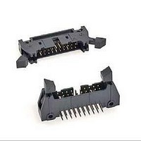
CONN HEADER 40POS STR LONG LATCH
Manufacturer
3M
Series
3000r
Specifications of 3432-2302
Contact Type
Male Pin
Connector Type
Header, Shrouded
Number Of Positions
40
Number Of Positions Loaded
All
Pitch
0.100" (2.54mm)
Number Of Rows
2
Row Spacing
0.100" (2.54mm)
Contact Mating Length
0.240" (6.10mm)
Mounting Type
Through Hole
Termination
Solder
Fastening Type
Latch, Long/Eject Hooks
Contact Finish
Gold
Contact Finish Thickness
30µin (0.76µm)
Color
Gray
Product Type
Headers - Latch / Eject
Mounting Style
Through Hole
Mounting Angle
Straight
Termination Style
Solder Pin
Housing Material
Glass Filled Polyester
Contact Material
Copper Alloy
Contact Plating
Gold
Current Rating
1 A
Lead Free Status / RoHS Status
Vendor undefined / RoHS non-compliant
Features
-
Lead Free Status / Rohs Status
Lead free / RoHS Compliant
Other names
05400719982
34322302
5400719982
54007199823
80610164347
34322302
5400719982
54007199823
80610164347


.100” × .100” Latch/Ejector, Straight and Right Angle
3
Electronic Solutions Division
Interconnect Solutions
http://www.3Mconnector.com
Notes:
1. Notches A & C will accomodate 3M Polarizing Keys (3M Part #3518 or N3518).
2. Accepts Rear and Front mounting hardware:
3. The recommended PCB hole size for the kinked tail positions on the .112 solder tail connector is .035 ± .002.
Rear Entry: #4-24 thread cutting screw, 3M Part #3341-5, .116 [2.95] dia mounting hole
Front Entry: (Prior to installation of latch on Straight Versions) #2-56 bolt and nut, 3M Part #3341-6,
.106 [2.69] dia mounting hole
Kink is located .05” below bottom surface of plastic. External radius of kink toward part centerline
“Y”
Number Suffix
.100 ± .003
[2.54]
C L
3M Part
[1.52]
.060
-1XX2
-2XX2
-1X03
-2X03
Pin Qty
.300
[7.62]
Side to Side Stackability
Recommended Mounting Hole Pattern
10
14
16
20
26
34
40
50
60
64
0.94 (2.39) to .125
Thick PC Board
(3.18) Thick PC
Contact Tail
Solder Tail for
Solder Tail for
.062 (1.57)
Number
3M Part
Board
3793
3314
3408
3428
3429
3431
3432
3433
3372
3764
Ø.106
Position 1
[2.69]
(Straight)
.100 ± .003
[2.54]
(See Note 2)
B
[8.94]
.352
or
1.26 (32.1)
1.46 (37.2)
1.76 (44.8)
2.46 (62.6)
2.76 (70.2)
3.96 (100.7)
1.56 (39.7)
2.06 (52.4)
3.26 (82.9)
3.76 (95.6)
G Dim
Dimension E
A
Ø.116
[2.95]
(2.84)
(3.94)
.112
.155
1.105 (28.07)
1.305 (33.15)
1.405 (35.69)
1.605 (40.77)
1.905 (48.39)
2.305 (58.55)
2.605 (66.17)
3.105 (78.87)
3.605 (91.57)
3.805 (96.65)
Dimension F
.0245 ± .0005
.0245 ± .0005
Table 2
B
Table 1
(0.622)
(0.622)
Dimensions
Pin Cross Section
“Y”
0.865 (21.97)
1.065 (27.05)
1.165 (29.59)
1.365 (34.67)
1.665 (42.29)
2.065 (52.45)
2.365 (60.07)
2.865 (72.77)
3.365 (85.47)
3.565 (90.55)
Diagonals
.028 ± .001
.028 ± .001
(0.71)
(0.71)
C
.100 ± .003
[2.54]
C L
[0.74]
.029
For technical, sales or ordering information call
Recommended Mounting Hole Pattern
.41
[10.4]
Max to Edge of PCB
for Daisy Chain
Corner Radii
0.71 (18.0)
0.91 (23.1)
1.01 (25.6)
1.21 (30.7)
1.51 (38.3)
1.91 (48.5)
2.21 (56.1)
2.71 (68.8)
3.21 (81.5)
3.41 (86.6)
.0075 Ref
.0075 Ref
(0.191)
(0.191)
D
3M is a trademark of 3M Company.
(Right Angle)
Ø.106
.100 ± .003
[2.54]
[2.69]
Position 1
(See Note 2)
Polarizing
Notches
(0.89) (See Note 3)
0.035 ± .003 (0.89)
ABC
ABC
ABC
ABC
ABC
ABC
ABC
ABC
Dimension G
BC
BC
Inch
[5.89]
.232
C
Tolerance Unless Noted
0.035 ± .003
or
G Dim
[ ] Dimensions for
Reference only
Ø.116
± .1
[2.95]
.0
(mm)
Inch
3000 Series
± .01
800-225-5373
.00
Sheet 3 of 5
TS-0771-D
± .005
.000
Related parts for 3432-2302
Image
Part Number
Description
Manufacturer
Datasheet
Request
R

Part Number:
Description:
PROTECT HEADER STRT 40 CONTACT
Manufacturer:
3M
Datasheet:

Part Number:
Description:
CONN HEADER 40POS R/A LONG LATCH
Manufacturer:
3M
Datasheet:

Part Number:
Description:
CONN HEADER 40PS STR SHORT LATCH
Manufacturer:
3M
Datasheet:
Part Number:
Description:
CONN HEADER STKD 40POS R/A
Manufacturer:
3M
Datasheet:

Part Number:
Description:
CONN HEADER STKD 40POS R/A SH
Manufacturer:
3M
Datasheet:
Part Number:
Description:
3M-MINI-CLAMP/PLUG/WMIC/2MM/3POS/TYPE A/ORANGE/3M LOGO
Manufacturer:
3M
Datasheet:
Part Number:
Description:
3M-MINI-CLAMP/PLUG/WMIC/2MM/4POS/TYPE A/YELLOW/3M LOGO
Manufacturer:
3M
Datasheet:
Part Number:
Description:
3M-MINI-CLAMP/PLUG/WMIC/2MM/4POS/TYPE A/ORANGE/3M LOGO
Manufacturer:
3M
Datasheet:
Part Number:
Description:
3M-MINI-CLAMP/SKT PANELMOUNT/WMIC/2MM/3POS/TYPE A/RED/3M LOGO
Manufacturer:
3M
Datasheet:
Part Number:
Description:
3M-MINI-CLAMP/SKT PANELMOUNT/WMIC/2MM/3POS/TYPE A/YELLOW/3M LO
Manufacturer:
3M
Datasheet:
Part Number:
Description:
3M-MINI-CLAMP/SKT/WMIC/2MM/3POS/TYPE A/ORANGE/3M LOGO
Manufacturer:
3M
Datasheet:
Part Number:
Description:
3M-MINI-CLAMP/SKT PANELMOUNT/WMIC/2MM/3POS/TYPE A/ORANGE/3M LO
Manufacturer:
3M
Datasheet:
Part Number:
Description:
3M-MINI-CLAMP/SKT PANELMOUNT/WMIC/2MM/4POS/TYPE A/RED/3M LOGO
Manufacturer:
3M
Datasheet:
Part Number:
Description:
3M-MINI-CLAMP/SKT/WMIC/2MM/4POS/TYPE A/YELLOW/3M LOGO
Manufacturer:
3M
Datasheet:
Part Number:
Description:
3M-MINI-CLAMP/SKT PANELMOUNT/WMIC/2MM/4POS/TYPE A/YELLOW/3M LO
Manufacturer:
3M
Datasheet: