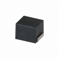
SMD Inductors(Coils)
For Signal Line(Wound)
NLV Series NLV25
FEATURES
• The product has good heat durability that withstands lead-free
• Lead-free material is used for the plating on the terminal
• The electrical characteristics, reliability, shape and pad shape
• The product uses metal terminals, which realize excellent
• Highly heat resistant thermoplastic resin is used to form the
• From 0.01µH to 100µH, all of the products in the E-12 series are
• This product is in compliance with the RoHS Directive. Other
APPLICATIONS
• Audio-visual equipment including TVs, VCRs and digital
• Electronic equipment used in communication infrastructures
• Electronic equipment used in onboard automobile equipment
• Other electronic equipment including HDDs and ODDs.
SPECIFICATIONS
Operating temperature range
Storage temperature range
RECOMMENDED SOLDERING CONDITIONS
REFLOW SOLDERING
• Conformity to RoHS Directive: This means that, in conformity with EU Directive 2002/95/EC, lead, cadmium, mercury, hexavalent chromium, and specific
• All specifications are subject to change without notice.
255˚C
230˚C
180˚C
150˚C
bromine-based flame retardants, PBB and PBDE, have not been used, except for exempted applications.
compatible reflow soldering conditions.
are the same as the previous NL series.
connection reliability.
exterior package.
J(±5%) tolerance products.
products with specifications that do not include exemption
regulations are also available.
cameras.
including xDSL and mobile base stations.
including car audio and ECU systems.
Pre-heating
90 to 120s
Time ( s )
10s max.
40s max.
–40 to +105°C
[Including self-temperature rise]
–40 to +105°C
Natural
cooling
FLOW SOLDERING
IRON SOLDERING
Tip temperature
Heating time
Soldering rod specifications
•
• Please contact us for details.
PRODUCT IDENTIFICATION
(1) Series name
(2) Dimensions
(3) Packaging style
(4) Inductance value
(5) Inductance tolerance
(6) Lead-free compatible product
PACKAGING STYLE AND QUANTITIES
Packaging style
Taping
NLV 25 T- 2R2
260˚C max.
170˚C
150˚C
(1)
Based on the above conditions, use a maximum product temperature of
260°C and a maximum accumulated heating time of 10 seconds as a
guideline.
25
T
010
R10
1R0
100
101
J
PF
EF
(2) (3)
Pre-heating
60 to 120s
(4) (5)
Time ( s )
J - PF
10s max.
(6)
300 to 350°C
3 secconds/soldering
Output: 30W Tip diameter: 1mm
Quantity
2000 pieces/reel
2.5× 2.0× 1.8mm (L× W× T)
Taping (reel)
0.01µH
0.1µH
1µH
10µH
100µH
±5%
Conformity to RoHS directive,
exemption regulations apply
Conformity to RoHS directive
Natural
cooling
002-09 / 20080708 / e511_nlv25.fm
Conformity to RoHS Directive
(1/3)


