B82498F1102J EPCOS Inc, B82498F1102J Datasheet
B82498F1102J
Specifications of B82498F1102J
B82498F1102J000
Available stocks


Related parts for B82498F1102J


B82498F1102J Summary of contents
Page 1
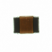
SMT inductors SIMID series, SIMID 0805-F Series/Type: B82498F Date: March 2008 Data Sheet Data Sheet EPCOS AG 2008. Reproduction, publication and dissemination of this publication, enclosures hereto and the information contained therein without EPCOS’ prior express consent is prohibited. ...
Page 2
SMT inductors, SIMID series SIMID 0805-F Size 0805 (EIA) and/or 2012 (IEC) Rated inductance 2 6800 nH Rated current 1000 mA Construction ■ Cubic coil with ceramic or ferrite core ■ Epoxy-molded flat top for ...
Page 3
SMT inductors, SIMID series SIMID 0805-F Dimensional drawing and layout recommendation 2.3 max. 2+0.2 Metallization Welding area Epoxy coating 1) 1) 0.5±0.1 0.5±0.1 1) Soldering area 2) This area (30% of contact area) should not be used to assess solderability ...
Page 4
SMT inductors, SIMID series SIMID 0805-F Technical data and measuring conditions Rated inductance factor Q min Rated temperature T R Rated current I R Self-resonance frequency f res,min DC resistance R max Solderability (lead-free) Resistance to soldering ...
Page 5
SMT inductors, SIMID series SIMID 0805-F Characteristics and ordering codes L Tolerance MHz Core material: ceramic ±10% 2 250 5.6 250 6.8 250 8.2 250 ± 250 ^ ±5% 12 250 J ...
Page 6
... R 6 03/08 B82498F 1) f Ordering code res,min (standard version) MHz 440 B82498F1102J000 420 B82498F1122J000 380 B82498F1152J000 350 B82498F1182J000 330 B82498F1222J000 270 B82498F1272J000 250 B82498F1332J000 230 B82498F1392J000 210 B82498F1472J000 180 B82498F1562J000 140 B82498F1682J000 ...
Page 7
SMT inductors, SIMID series SIMID 0805-F Impedance |Z| vs. frequency f (ceramic core) measured with impedance analyzer Agilent 4291A, typical values at 20 ° B82498F Ω | 820 nH 3 470 nH 10 100 nH 2 ...
Page 8
SMT inductors, SIMID series SIMID 0805-F Inductance L versus DC load current I measured with RF LCR meter Agilent 4275A, typical values at 20 ° 6.8 µH µH 4.7 µH L 2.7 µH 1 µ 0.82 ...
Page 9
Cautions and warnings ■ Please note the recommendations in our Inductors data book (latest edition) and in the data sheets. – Particular attention should be paid to the derating curves given there. – The soldering conditions should also be observed. ...
Page 10
Important notes The following applies to all products named in this publication: 1. Some parts of this publication contain statements about the suitability of our products for certain areas of application. These statements are based on our knowledge of typical ...