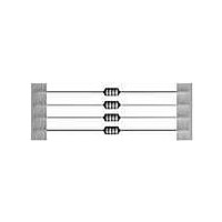
B78108S1334J EPCOS Inc, B78108S1334J Datasheet - Page 4

B78108S1334J
Manufacturer Part Number
B78108S1334J
Description
CHOKE RF 330UH 190MA AXIAL
Manufacturer
EPCOS Inc
Series
BCr
Type
Ferrite Corer
Specifications of B78108S1334J
Inductance
330µH
Tolerance
±5%
Current
190mA
Dc Resistance (dcr)
6.4 Ohm Max
Q @ Freq
70 @ 796kHz
Self Resonant Freq
2.7MHz
Package / Case
Axial
Mounting Type
Through Hole
Frequency - Test
796kHz
Material - Core
Ferrite Drum
Applications
General Purpose
Maximum Dc Current
190 mAmps
Maximum Dc Resistance
6.4 Ohms
Self Resonant Frequency
2.7 MHz
Q Minimum
70
Termination Style
Axial
Inductance Tolerance
± 5%
Dc Resistance Max
6.4ohm
Dc Current Rating
190mA
Q Test Frequency
0.796MHz
Inductor Case Style
Axial Leaded
No. Of Pins
2
Svhc
No SVHC (18-Jun-2010)
Rohs Compliant
Yes
Body Diameter
4mm
Lead Free Status / RoHS Status
Lead free / RoHS Compliant
Shielding
-
Current - Saturation
-
Current - Temperature Rise
-
Lead Free Status / Rohs Status
Lead free / RoHS Compliant
Other names
B78108S1334J000
2
2.1
For as long as electronic transmission equipment such as radio, television, and telephone has been
in existence, it has had a history of susceptibility to interference from other electronic devices. Legal
regulations on interference suppression (electromagnetic and radio frequency interference, EMI
and RFI) have been in existence since 1928. These regulations protect transmission paths and re-
ception equipment by limiting the emitted interference.
In view of the increasing number of electrical and electronic appliances in use, not only the princi-
ples of interference suppression must be observed, but also, in the sense of electromagnetic com-
patibility (EMC), it must be ensured that all equipment is able to operate simultaneously without
problems. EMC is defined as the ability of electrical equipment to function satisfactorily in its elec-
tromagnetic environment without affecting other equipment in this environment to an impermissible
extent.
The European Communities’ EMC Directive (89/336/EEC) came into force on the 1. 1. 1996. It has
been transformed into corresponding legislation in the individual EU (European Union) member
states. With this, it has become mandatory to design electronic equipment to comply with the pro-
tection objectives of this Directive; i.e. to meet the requirements for electromagnetic emission and
electromagnetic immunity as laid down in the corresponding EN standards (European Standards).
The concept of EMC includes both electromagnetic emission (EME) and electromagnetic immunity/
susceptibility (EMS), see
Fig. 3
An interference source may generate conducted or radiated electromagnetic energy, i.e. conducted
emission (CE) or radiated emission (RE). This also applies to the propagation paths and to the elec-
tromagnetic susceptibility of disturbed equipment.
In order to work out economical solutions, it is necessary consider both phenomena, i.e. propaga-
tion and susceptibility, to an equal extent, and not just one aspect, e.g. conducted emission.
General Technical Information
Interference
Emission
EME
source
CE
RE
Electromagnetic compatibility (EMC)
Introduction
EMC terms
Propagation
Conducted
fig.
Radiated
EMC
3.
Susceptibility
equipment
Disturbed
EMS
12
CS
RS
04/00
EMC = Electromagnetic
EME = Electromagnetic
EMS = Electromagnetic
CE
CS
RE
RS
= Conducted emission
= Susceptibility to
= Radiated emission
= Susceptibility to
compatibility
emission
immunity/susceptibility
conducted emission
radiated emission


