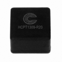
HCPT1309-R20-R Coiltronics/Div of Cooper/Bussmann, HCPT1309-R20-R Datasheet

HCPT1309-R20-R
Manufacturer Part Number
HCPT1309-R20-R
Description
INDUCTOR HIGH CURRENT 0.20UH
Manufacturer
Coiltronics/Div of Cooper/Bussmann
Series
HCPT1309r
Type
Powdered Iron Corer
Datasheet
1.HCPT1309-1R0-R.pdf
(2 pages)
Specifications of HCPT1309-R20-R
Inductance
200nH
Current
43.1A
Current - Saturation
90A
Tolerance
±20%
Dc Resistance (dcr)
0.426 mOhm
Package / Case
Radial
Mounting Type
Through Hole
Operating Temperature
-40°C ~ 105°C
Frequency - Test
100kHz
Material - Core
Powdered Iron
Applications
General Purpose
Lead Free Status / RoHS Status
Lead free / RoHS Compliant
Shielding
-
Q @ Freq
-
Self Resonant Freq
-
Current - Temperature Rise
-
Other names
513-1518
HCPT1309-R20-R
HCPT1309-R20-R
Description
• 105°C maximum total temperature operation
• 13.2mm x 13.2mm x 9.0mm through hole
• Core material: Powder Iron
• Inductance range from 0.20µH to 3.3µH
• Current range from 90.0 Amps to 11.4 Amps
• Frequency range up to 1MHz
Applications
• Next generation processors
• High current DC-DC converters
• VRM, multi-phase buck regulator
• Desktop computers
• Video game power
Environmental Data
• Storage temperature range: -40°C to +105°C
• Operating temperature range: -40°C to +105°C
• Solder reflow temperature: +260°C max. for 10 seconds
(1) OCL: Open Circuit Inductance test parameters: 100kHz, 0.1Vrms, 0.0Adc.
(2) Irms: DC current for an approximate ∆T of 40°C without core loss. Derating is
Mechanical Diagrams
Part Number
HCPT1309-R20-R
HCPT1309-R47-R
HCPT1309-1R0-R
HCPT1309-1R5-R
HCPT1309-2R2-R
HCPT1309-3R3-R
package
(range is application specific)
maximum
necessary for AC currents. PCB layout, trace thickness and width, air-flow, and
proximity of other heat generating components will affect the temperature rise. It
is recommended that the temperature of the part not exceed 105°C under worst
case operating conditions verified in the end application.
HCPT1309-R20
HCPT1309-R47
HCPT1309-1R0
HCPT1309-1R5
HCPT1309-2R2
HCPT1309-3R3
Part No
HCPT1309-xxx
wwllyy R
nominal +/-
20% (µH)
OCL (1)
TOP VIEW
"A " MAX
0.20
0.49
0.96
1.59
2.27
3.31
Dimension Table
14.0
14.0
13.7
13.5
13.5
13.5
"A "
12.2
12.2
12.0
11.8
11.8
11.8
"B"
13.2 sq
Amperes
MAX
Irms (2)
43.1
34.0
19.4
13.7
12.5
11.4
"C"
1.63
1.63
1.29
1.15
1.15
1.15
2.13
2.13
1.6
1.40
1.40
1.40
"D"
FRONT VIEW
"B" +/- 1.0
Isat Amperes (3)
rolloff @20°C
2002/95/EC
Peak 20%
RoHS
RECOMMENDED PCB PAD LAYOUT
72.2
43.3
30.9
24.1
19.7
16.7
(3) Isat Amperes peak for approximately 20% rolloff (@20°C)
(4) Isat Amperes peak for approximately 30% rolloff (@20°C)
(5) K-factor: Used to determine B p-p for core loss (see graph).
Packaging
• Supplied in bulk packaging, 100 parts per tray
B p-p = K*L*∆I, B p-p: (Gauss), K: (K factor from table), L: (Inductance in uH),
∆I (Peak to peak ripple current in Amps).
"B" +/- 1.0
"C" typ
Isat Amperes (4)
max
9.0
rolloff @20°C
3.5 +/- 0.5
Peak 30%
90.0
55.0
40.0
30.6
25.0
21.0
2
ØD
B O T TO M V I E W
nom @20°C
DCR (mΩ)
0.426
0.624
1.90
3.82
4.10
4.80
1
wwllyy = Date Code. R = Revision Level.
2
SCHEMATIC
HCPT1309 Series
Power Inductors
Dimensions are in millimeters.
1
K-factor
154.1
92.4
66.0
51.4
42.0
35.6
(5)
Related parts for HCPT1309-R20-R
HCPT1309-R20-R Summary of contents
Page 1
... Storage temperature range: -40°C to +105°C • Operating temperature range: -40°C to +105°C (range is application specific) • Solder reflow temperature: +260°C max. for 10 seconds maximum Part Number OCL (1) nominal +/- 20% (µH) HCPT1309-R20-R 0.20 HCPT1309-R47-R 0.49 HCPT1309-1R0-R 0.96 HCPT1309-1R5-R 1.59 HCPT1309-2R2-R 2 ...
Page 2
... Core Loss vs. B p-p 500 750 1000 1250 1500 1750 2000 B p-p (Gauss) OCL vs Isat 100 % of Isat HCPT1309 Series Power Inductors 200kHz 300kHz 400kHz 500kHz 600kHz 700kHz 800kH 900kHz 1.0MHz 2250 2500 2750 120 140 160 ...


