ATTINY24V-10PU Atmel, ATTINY24V-10PU Datasheet - Page 24
ATTINY24V-10PU
Manufacturer Part Number
ATTINY24V-10PU
Description
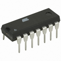
IC MCU AVR 2K FLASH 10MHZ 14-DIP
Manufacturer
Atmel
Series
AVR® ATtinyr
Specifications of ATTINY24V-10PU
Core Processor
AVR
Core Size
8-Bit
Speed
10MHz
Connectivity
USI
Peripherals
Brown-out Detect/Reset, POR, PWM, Temp Sensor, WDT
Number Of I /o
12
Program Memory Size
2KB (1K x 16)
Program Memory Type
FLASH
Eeprom Size
128 x 8
Ram Size
128 x 8
Voltage - Supply (vcc/vdd)
1.8 V ~ 5.5 V
Data Converters
A/D 8x10b
Oscillator Type
Internal
Operating Temperature
-40°C ~ 85°C
Package / Case
14-DIP (0.300", 7.62mm)
Processor Series
ATTINY2x
Core
AVR8
Data Bus Width
8 bit
Data Ram Size
128 B
Interface Type
SPI
Maximum Clock Frequency
10 MHz
Number Of Programmable I/os
12
Number Of Timers
2
Operating Supply Voltage
1.8 V to 5.5 V
Maximum Operating Temperature
+ 85 C
Mounting Style
Through Hole
Minimum Operating Temperature
- 40 C
On-chip Adc
8-ch x 10-bit
Cpu Family
ATtiny
Device Core
AVR
Device Core Size
8b
Frequency (max)
10MHz
Total Internal Ram Size
128Byte
# I/os (max)
12
Number Of Timers - General Purpose
2
Operating Supply Voltage (typ)
2.5/3.3/5V
Operating Supply Voltage (max)
5.5V
Operating Supply Voltage (min)
1.8V
Instruction Set Architecture
RISC
Operating Temp Range
-40C to 85C
Operating Temperature Classification
Industrial
Mounting
Through Hole
Pin Count
14
Package Type
PDIP
Package
14PDIP
Family Name
ATtiny
Maximum Speed
10 MHz
For Use With
ATSTK600-DIP40 - STK600 SOCKET/ADAPTER 40-PDIP770-1007 - ISP 4PORT ATMEL AVR MCU SPI/JTAGATAVRISP2 - PROGRAMMER AVR IN SYSTEMATSTK505 - ADAPTER KIT FOR 14PIN AVR MCU
Lead Free Status / RoHS Status
Lead free / RoHS Compliant


9.7
9.8
9.9
9.10
24
Rev E. 09/06
Rev D. 08/06
Rev C. 07/06
Rev B. 05/06
ATtiny24/44/84
6.
7.
8.
9.
1.
2.
3.
4.
5.
6.
7.
8.
9.
10.
1.
2.
3.
4.
5.
6.
1.
2.
3.
4.
1.
2.
3.
4.
5.
6.
Updated bit5 name in
Updated bit5 in
Updated
Updated step 5 in
All characterization data moved to
All Register Descriptions gathered up in separate sections at the end of each chapter.
Updated
Updated
12-3 on page 109
Updated
Updated
Updated
Added note in
Updated
Updated
Updated
Updated
Added
Updated code examples in
Updated code examples in
Updated
Updated Features in
Added
Updated Bit description in
Added note to
Updated
Updated
Updated
Table 19-5 on page
11 on page
Updated Features in
Updated Operation in
Updated
Table 20-2 on page
“Clock speed considerations” on page
“SPI Master Operation Example” on page
“System Control and Reset” on page
Table 11-3 on page
“Fast PWM Mode” on page
Figure 12-7 on page 98
“Analog Comparator Multiplexed Input” on page
“Electrical Characteristics” on page
“Typical Characteristics” on page
“Calibrated Internal 8 MHz Oscillator” on page
“OSCCAL – Oscillator Calibration Register” on page
“Signature Bytes” on page
“Default Clock Source” on page 30
“Power Reduction Register” on page
“Temperature Measurement” on page
Table 20-4 on page
182.
Table 19-12 on page
Table 18-1 on page
“TIFR1 – Timer/Counter Interrupt Flag Register 1” on page
“Enter High-voltage Serial Programming Mode” on page
and
161,
“USI – Universal Serial Interface” on page
“Analog to Digital Converter” on page
“TIFR1 – Timer/Counter Interrupt Flag Register 1” on page
“Analog to Digital Converter” on page
Table 12-5 on page
Table 19-12 on page
“ADMUX – ADC Multiplexer Selection Register” on page
176.
“SPI Master Operation Example” on page
“SPI Slave Operation Example” on page
81,
177,
Table 11-6 on page
and
“Electrical Characteristics” on page
157.
165.
162.
Table 9-4 on page
97.
Figure 16-1 on page
185.
110.
174.
123.
165,
35.
39.
144.
119.
Table 19-16 on page
82,
26.
42,
Table 11-8 on page
129.
133.
132.
132.
Table 16-3 on page
30.
117.
121.
119.
174.
171,
8006KS–AVR–10/10
168.
114.
Table 20-
83,
114.
Table
145,
145.
Related parts for ATTINY24V-10PU
Image
Part Number
Description
Manufacturer
Datasheet
Request
R

Part Number:
Description:
IC MCU AVR 2K FLASH 10MHZ 20-QFN
Manufacturer:
Atmel
Datasheet:

Part Number:
Description:
IC MCU AVR 2K FLASH 10MHZ 14SOIC
Manufacturer:
Atmel
Datasheet:

Part Number:
Description:
MCU AVR 2KB FLASH 10MHZ 14SOIC
Manufacturer:
Atmel
Datasheet:
Part Number:
Description:
MCU AVR 2KB FLASH 10MHZ 20QFN
Manufacturer:
Atmel
Datasheet:

Part Number:
Description:
8-bit Avr Microcontroller With 2/4/8k Bytes Insystem Programmable Flash
Manufacturer:
ATMEL Corporation
Datasheet:
Part Number:
Description:
8-bit Microcontrollers - MCU Microcontroller
Manufacturer:
Atmel
Part Number:
Description:
Manufacturer:
Atmel Corporation
Datasheet:
Part Number:
Description:
Manufacturer:
Atmel Corporation
Datasheet:
Part Number:
Description:
IC MCU AVR 2K FLASH 20MHZ 20-QFN
Manufacturer:
Atmel
Datasheet:
Part Number:
Description:
IC MCU AVR 2K FLASH 20MHZ 14SOIC
Manufacturer:
Atmel
Datasheet:

Part Number:
Description:
MCU AVR 2K FLASH 15MHZ 20-QFN
Manufacturer:
Atmel
Datasheet:

Part Number:
Description:
IC MCU AVR 2K FLASH 20MHZ 14-DIP
Manufacturer:
Atmel
Datasheet: