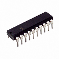
PIC18LF13K22-I/P Microchip Technology, PIC18LF13K22-I/P Datasheet - Page 7

PIC18LF13K22-I/P
Manufacturer Part Number
PIC18LF13K22-I/P
Description
IC PIC MCU FLASH 256KX8 20-PDIP
Manufacturer
Microchip Technology
Series
PIC® XLP™ 18Fr
Datasheets
1.PIC18LF13K22-ISS.pdf
(388 pages)
2.PIC18LF13K22-ISS.pdf
(12 pages)
3.PIC18LF13K22-ISS.pdf
(36 pages)
4.PIC18LF14K22-IP.pdf
(382 pages)
Specifications of PIC18LF13K22-I/P
Program Memory Type
FLASH
Program Memory Size
8KB (4K x 16)
Package / Case
20-DIP (0.300", 7.62mm)
Core Processor
PIC
Core Size
8-Bit
Speed
64MHz
Connectivity
I²C, LIN, SPI, UART/USART
Peripherals
Brown-out Detect/Reset, POR, PWM, WDT
Number Of I /o
17
Eeprom Size
256 x 8
Ram Size
256 x 8
Voltage - Supply (vcc/vdd)
1.8 V ~ 3.6 V
Data Converters
A/D 12x10b
Oscillator Type
Internal
Operating Temperature
-40°C ~ 85°C
Processor Series
PIC18LF
Core
PIC
Data Bus Width
8 bit
Data Ram Size
256 B
Interface Type
I2C, MSSP, SPI, USART
Maximum Clock Frequency
32 KHz
Number Of Programmable I/os
18
Number Of Timers
4
Operating Supply Voltage
1.8 V to 3.6 V
Maximum Operating Temperature
+ 125 C
Mounting Style
Through Hole
3rd Party Development Tools
52715-96, 52716-328, 52717-734, 52712-325, EWPIC18
Development Tools By Supplier
PG164130, DV164035, DV244005, DV164005
Minimum Operating Temperature
- 40 C
On-chip Adc
10 bit, 12 Channel
Lead Free Status / RoHS Status
Lead free / RoHS Compliant
Lead Free Status / RoHS Status
Lead free / RoHS Compliant, Lead free / RoHS Compliant
2010 Microchip Technology Inc.
4.5
Affected Silicon Revisions
4.6
Affected Silicon Revisions
4.7
Affected Silicon Revisions.
A3
A3
A3
X
X
X
cleared by hardware if improper Stop is
received on the bus.
Work around
the SSPEN bit of SSPCON1.
configured
<3:0> = 0011), the first SPI high time may
be short.
Work around
SSPBUF is written to while shifting out data,
a ninth SCK pulse is incorrectly generated.
At that point, the module locks the user from
writing to the SSPBUF register, but a write
attempt will still cause 8 or 9 more SCK
pulses to be generated.
Work around
correctly set to indicate that there was a write
collision. Any time this bit is set, the module
must be disabled and enabled (toggle
SSPEN) to return to the correct operation.
The bus will remain out of synchronization.
In I
Reset the module via clearing and setting
In SPI Master mode, when the SPI clock is
Option 1: Ensure TMR2 value rolls over to
Option 2: Turn Timer2 off and clear TMR2
In any SPI Master mode, SCK = TMR2/2, if
The WCOL bit of the SSPCON register is
A7
A7
A7
X
X
X
2
C Master mode, the RCEN bit is not
A8
A8
A8
X
X
X
zero immediately before writing to
SSPBUF.
before writing SSPBUF. Enable
TMR2 after SSPBUF is written.
for
Timer2/2
(SSPCON1
PIC18F1XK22/LF1XK22
5. Module: In-Circuit Serial Programming™
6. Module: Oscillator
7. Module: PORTB Interrupt-on-Change
The device cannot be programmed using ICSP
when the device V
Work around
Ensure that the device voltage is 2.0V or higher
when programming the device.
Affected Silicon Revisions
6.1
6.2
Work around
The IESO Configuration bit must also be set
when the FCMEN Configuration bit is set.
Affected Silicon Revisions
Setting a PORTB interrupt-on-change enable bit of
the IOCB register while the corresponding PORTB
input is high will cause an RBIF interrupt.
Work around
Set the IOCB bits to the desired configuration, then
read PORTB to clear the mismatch latches.
Finally, clear the RBIF bit before setting the RBIE
bit.
Affected Silicon Revisions
A3
A3
A3
X
X
X
and the IESO Configuration bit is not set,
then a clock failure during Sleep will not be
detected.
Clock Switching
When the FCMEN Configuration bit is set
A7
A7
A7
X
X
X
(ICSP™)
A8
A8
A8
X
X
X
DD
is less than 2.0V.
DS80437D-page 7


