PIC18F14K22-I/ML Microchip Technology, PIC18F14K22-I/ML Datasheet - Page 3
PIC18F14K22-I/ML
Manufacturer Part Number
PIC18F14K22-I/ML
Description
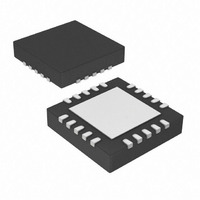
IC PIC MCU FLASH 512KX16 20-QFN
Manufacturer
Microchip Technology
Series
PIC® XLP™ 18Fr
Datasheets
1.PIC16F722-ISS.pdf
(8 pages)
2.PIC18LF13K22-ISS.pdf
(388 pages)
3.PIC18LF13K22-ISS.pdf
(12 pages)
4.PIC18LF13K22-ISS.pdf
(36 pages)
5.PIC18F13K22-ISS.pdf
(382 pages)
Specifications of PIC18F14K22-I/ML
Core Size
8-Bit
Program Memory Size
16KB (8K x 16)
Core Processor
PIC
Speed
64MHz
Connectivity
I²C, LIN, SPI, UART/USART
Peripherals
Brown-out Detect/Reset, POR, PWM, WDT
Number Of I /o
17
Program Memory Type
FLASH
Eeprom Size
256 x 8
Ram Size
512 x 8
Voltage - Supply (vcc/vdd)
1.8 V ~ 5.5 V
Data Converters
A/D 12x10b
Oscillator Type
Internal
Operating Temperature
-40°C ~ 85°C
Package / Case
20-VQFN Exposed Pad, 20-HVQFN, 20-SQFN, 20-DHVQFN
Controller Family/series
PIC18
No. Of I/o's
18
Eeprom Memory Size
256Byte
Ram Memory Size
512Byte
Cpu Speed
64MHz
No. Of Timers
4
Processor Series
PIC18F
Core
PIC
Data Bus Width
8 bit
Data Ram Size
512 B
Interface Type
I2C, MSSP, SPI, USART
Maximum Clock Frequency
64 MHz
Number Of Programmable I/os
17
Number Of Timers
4
Operating Supply Voltage
1.8 V to 5.5 V
Maximum Operating Temperature
+ 125 C
Mounting Style
SMD/SMT
3rd Party Development Tools
52715-96, 52716-328, 52717-734, 52712-325, EWPIC18
Development Tools By Supplier
PG164130, DV164035, DV244005, DV164005
Minimum Operating Temperature
- 40 C
On-chip Adc
10 bit, 12 Channel
Package
20QFN EP
Device Core
PIC
Family Name
PIC18
Maximum Speed
64 MHz
A/d Bit Size
10 bit
A/d Channels Available
12
Height
0.88 mm
Length
4 mm
Supply Voltage (max)
5.5 V
Supply Voltage (min)
1.8 V, 2.7 V
Width
4 mm
Lead Free Status / RoHS Status
Lead free / RoHS Compliant
Lead Free Status / RoHS Status
Lead free / RoHS Compliant, Lead free / RoHS Compliant
Available stocks
Company
Part Number
Manufacturer
Quantity
Price

Part Number:
PIC18F14K22-I/ML
Manufacturer:
MICROCHIP/微芯
Quantity:
20 000


Silicon Errata Issues
1. Module: ADC (Analog-to-Digital
2010 Microchip Technology Inc.
Note:
1.1
Affected Silicon Revisions
A3
X
large INL error up to approximately 8 LSb.
Work around
None for the AN3 pin. For better accuracy,
use another analog pin.
ADC conversion on AN3/OSC2 will have
This document summarizes all silicon
errata issues from all revisions of silicon,
previous as well as current. Only the
issues indicated by the shaded column in
the following tables apply to the current
silicon revision (A8).
A7
X
Converter)
A8
X
PIC18F1XK22/LF1XK22
1.2
1. When F
2. The ADC is operating from its dedicated
Work around
Method 1:
Method 2: Select the dedicated FRC
Method 3: Method 3 is provided if the
these conditions:
An ADC conversion may not complete under
the clock source used for the ADC
converter.
internal FRC oscillator and the device is
not in Sleep mode (an F
When this occurs, the ADC Interrupt
Fag (ADIF) does not get set, the GO/
DONE bit does not get cleared, and the
conversion result does not get loaded
into the ADRESH and ADRESL result
registers.
OSC
as the ADC clock source and
reduce the F
MHz or less when performing
ADC conversions.
oscillator
conversion clock source and
perform all conversions with the
device in Sleep.
application cannot use Sleep
mode and requires continuous
operation at frequencies above
8 MHz. This method requires
early termination of an ADC
conversion. Provide a fixed time
delay in software to stop the A-
to-D conversion manually, after
all 10 bits are converted, but
before the conversion would
complete
conversion
clearing the GO/DONE bit in
software. The GO/DONE bit
must be cleared during the last
½
conversion
completed automatically. Refer
to Figure 1 for details.
Select the system clock, F
is greater than 8 MHz and is
T
AD
cycle,
automatically.
OSC
as
OSC
is
DS80437D-page 3
would
frequency to 8
frequency).
stopped
before
the
have
ADC
OSC
The
the
by
,
Related parts for PIC18F14K22-I/ML
Image
Part Number
Description
Manufacturer
Datasheet
Request
R

Part Number:
Description:
Manufacturer:
Microchip Technology Inc.
Datasheet:
Part Number:
Description:
Manufacturer:
Microchip Technology Inc.
Datasheet:
Part Number:
Description:
Manufacturer:
Microchip Technology Inc.
Datasheet:
Part Number:
Description:
Manufacturer:
Microchip Technology Inc.
Datasheet:
Part Number:
Description:
Manufacturer:
Microchip Technology Inc.
Datasheet:
Part Number:
Description:
Manufacturer:
Microchip Technology Inc.
Datasheet:
Part Number:
Description:
Manufacturer:
Microchip Technology Inc.
Datasheet:
Part Number:
Description:
Manufacturer:
Microchip Technology Inc.
Datasheet: