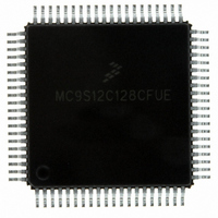
MC9S12C128CFUE Freescale Semiconductor, MC9S12C128CFUE Datasheet - Page 590

MC9S12C128CFUE
Manufacturer Part Number
MC9S12C128CFUE
Description
IC MCU 128K FLASH 25MHZ 80-QFP
Manufacturer
Freescale Semiconductor
Series
HCS12r
Specifications of MC9S12C128CFUE
Core Processor
HCS12
Core Size
16-Bit
Speed
25MHz
Connectivity
CAN, EBI/EMI, SCI, SPI
Peripherals
POR, PWM, WDT
Number Of I /o
60
Program Memory Size
128KB (128K x 8)
Program Memory Type
FLASH
Ram Size
4K x 8
Voltage - Supply (vcc/vdd)
2.35 V ~ 5.5 V
Data Converters
A/D 8x10b
Oscillator Type
Internal
Operating Temperature
-40°C ~ 85°C
Package / Case
80-QFP
Cpu Family
HCS12
Device Core Size
16b
Frequency (max)
25MHz
Interface Type
CAN/SCI/SPI
Total Internal Ram Size
4KB
# I/os (max)
60
Number Of Timers - General Purpose
8
Operating Supply Voltage (typ)
2.5/5V
Operating Supply Voltage (max)
2.75/5.5V
Operating Supply Voltage (min)
2.35/2.97V
On-chip Adc
8-chx10-bit
Instruction Set Architecture
CISC
Operating Temp Range
-40C to 85C
Operating Temperature Classification
Industrial
Mounting
Surface Mount
Pin Count
80
Package Type
PQFP
Processor Series
S12C
Core
HCS12
Data Bus Width
16 bit
Data Ram Size
4000 B
Maximum Clock Frequency
25 MHz
Number Of Programmable I/os
61
Number Of Timers
1
Operating Supply Voltage
- 0.3 V to + 6.5 V
Maximum Operating Temperature
+ 85 C
Mounting Style
SMD/SMT
3rd Party Development Tools
EWHCS12
Development Tools By Supplier
M68EVB912C32EE
Minimum Operating Temperature
- 40 C
Lead Free Status / RoHS Status
Lead free / RoHS Compliant
Eeprom Size
-
Lead Free Status / Rohs Status
Compliant
Available stocks
Company
Part Number
Manufacturer
Quantity
Price
Company:
Part Number:
MC9S12C128CFUE
Manufacturer:
ST
Quantity:
6 246
Company:
Part Number:
MC9S12C128CFUE
Manufacturer:
Freescale Semiconductor
Quantity:
10 000
- Current page: 590 of 690
- Download datasheet (4Mb)
Chapter 20 96 Kbyte Flash Module (S12FTS96KV1)
20.3.2.6
The FSTAT register defines the status of the Flash command controller and the results of command
execution.
In normal modes, bits CBEIF, PVIOL, and ACCERR are readable and writable, bits CCIF and BLANK
are readable and not writable, remaining bits, including FAIL and DONE, read 0 and are not writable. In
special modes, FAIL is readable and writable while DONE is readable but not writable. FAIL must be clear
in special modes when starting a command write sequence.
590
Module Base + 0x0005
Reset
CBEIF
Field
CCIF
7
6
W
R
CBEIF
Command Buffer Empty Interrupt Flag — The CBEIF flag indicates that the address, data and command
buffers are empty so that a new command write sequence can be started. The CBEIF flag is cleared by writing
a 1 to CBEIF. Writing a 0 to the CBEIF flag has no effect on CBEIF. Writing a 0 to CBEIF after writing an aligned
word to the Flash address space but before CBEIF is cleared will abort a command write sequence and cause
the ACCERR flag in the FSTAT register to be set. Writing a 0 to CBEIF outside of a command write sequence
will not set the ACCERR flag. The CBEIF flag is used together with the CBEIE bit in the FCNFG register to
generate an interrupt request (see
0 Buffers are full
1 Buffers are ready to accept a new command
Command Complete Interrupt Flag — The CCIF flag indicates that there are no more commands pending. The
CCIF flag is cleared when CBEIF is clear and sets automatically upon completion of all active and pending
commands. The CCIF flag does not set when an active commands completes and a pending command is
fetched from the command buffer. Writing to the CCIF flag has no effect. The CCIF flag is used together with the
CCIE bit in the FCNFG register to generate an interrupt request (see
0 Command in progress
1 All commands are completed
1. Allowed transitions marked with X.
Flash Status Register (FSTAT)
1
7
Protection
Scenario
From
6
7
= Unimplemented or Reserved
CCIF
1
6
Table 20-13. Flash Protection Scenario Transitions
Figure 20-12. Flash Status Register (FSTAT)
0
X
Table 20-14. FSTAT Field Descriptions
PVIOL
MC9S12C-Family / MC9S12GC-Family
0
5
X
X
1
Figure
ACCERR
X
20-28).
2
Rev 01.24
To Protection Scenario
0
4
Description
X
X
3
0
0
3
X
X
4
(1)
Figure
X
5
BLANK
0
2
20-28).
X
X
6
Freescale Semiconductor
FAIL
0
1
X
7
DONE
1
0
Related parts for MC9S12C128CFUE
Image
Part Number
Description
Manufacturer
Datasheet
Request
R
Part Number:
Description:
Manufacturer:
Freescale Semiconductor, Inc
Datasheet:
Part Number:
Description:
Manufacturer:
Freescale Semiconductor, Inc
Datasheet:
Part Number:
Description:
Manufacturer:
Freescale Semiconductor, Inc
Datasheet:
Part Number:
Description:
Manufacturer:
Freescale Semiconductor, Inc
Datasheet:
Part Number:
Description:
Manufacturer:
Freescale Semiconductor, Inc
Datasheet:
Part Number:
Description:
Manufacturer:
Freescale Semiconductor, Inc
Datasheet:
Part Number:
Description:
Manufacturer:
Freescale Semiconductor, Inc
Datasheet:
Part Number:
Description:
Manufacturer:
Freescale Semiconductor, Inc
Datasheet:
Part Number:
Description:
Manufacturer:
Freescale Semiconductor, Inc
Datasheet:
Part Number:
Description:
Manufacturer:
Freescale Semiconductor, Inc
Datasheet:
Part Number:
Description:
Manufacturer:
Freescale Semiconductor, Inc
Datasheet:
Part Number:
Description:
Manufacturer:
Freescale Semiconductor, Inc
Datasheet:
Part Number:
Description:
Manufacturer:
Freescale Semiconductor, Inc
Datasheet:
Part Number:
Description:
Manufacturer:
Freescale Semiconductor, Inc
Datasheet:
Part Number:
Description:
Manufacturer:
Freescale Semiconductor, Inc
Datasheet:


