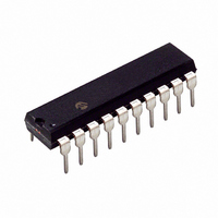
PIC16F631-I/P Microchip Technology, PIC16F631-I/P Datasheet - Page 6

PIC16F631-I/P
Manufacturer Part Number
PIC16F631-I/P
Description
IC PIC MCU FLASH 1KX14 20DIP
Manufacturer
Microchip Technology
Series
PIC® 16Fr
Datasheets
1.PIC16F616T-ISL.pdf
(8 pages)
2.PIC16F690DM-PCTLHS.pdf
(306 pages)
3.PIC16F677-IP.pdf
(2 pages)
4.PIC16F677-IP.pdf
(16 pages)
5.PIC16F677-ISO.pdf
(294 pages)
Specifications of PIC16F631-I/P
Program Memory Type
FLASH
Program Memory Size
1.75KB (1K x 14)
Package / Case
20-DIP (0.300", 7.62mm)
Core Processor
PIC
Core Size
8-Bit
Speed
20MHz
Peripherals
Brown-out Detect/Reset, POR, WDT
Number Of I /o
18
Eeprom Size
128 x 8
Ram Size
64 x 8
Voltage - Supply (vcc/vdd)
2 V ~ 5.5 V
Oscillator Type
Internal
Operating Temperature
-40°C ~ 85°C
Processor Series
PIC16F
Core
PIC
Data Bus Width
8 bit
Data Ram Size
64 B
Maximum Clock Frequency
20 MHz
Number Of Programmable I/os
17
Number Of Timers
2
Operating Supply Voltage
2 V to 5.5 V
Maximum Operating Temperature
+ 85 C
Mounting Style
Through Hole
3rd Party Development Tools
52715-96, 52716-328, 52717-734
Development Tools By Supplier
PG164130, DV164035, DV244005, DV164005, PG164120, ICE2000, DM163014, DM164120-4
Minimum Operating Temperature
- 40 C
Data Rom Size
128 B
Height
3.3 mm
Length
26.16 mm
Supply Voltage (max)
5.5 V
Supply Voltage (min)
4.5 V
Width
6.35 mm
Lead Free Status / RoHS Status
Lead free / RoHS Compliant
For Use With
658-1047-5 - BOARD EVALUATION ACCESSTOUCHAC162061 - HEADER INTRFC MPLAB ICD2 20PINAC164039 - MODULE SKT PROMATE II 20DIP/SOICACICE0203 - MPLABICE 20P 300 MIL ADAPTER
Data Converters
-
Connectivity
-
Lead Free Status / Rohs Status
Lead free / RoHS Compliant
Available stocks
Company
Part Number
Manufacturer
Quantity
Price
Company:
Part Number:
PIC16F631-I/P
Manufacturer:
MICROCHIP
Quantity:
4 500
Part Number:
PIC16F631-I/P
Manufacturer:
MICROCHIP/微芯
Quantity:
20 000
PIC16F631/677/685/687/689/690
2. Module: SSP (PIC16F687/689/690 only)
2.1 SSP module does not recognize first Start bit
EXAMPLE 1:
DS80243M-page 6
MOVLW
MOVWF
MOVLW
MOVWF
received.
In any of the I
to recognize the first Start bit received after a
transition from module disable to module enable.
Subsequent Stop bits and Start bits are detected
properly.
Work around
Enable the SSP module in SSPMSK Access mode
before changing the mode to the desired I
operation.
Fix
Rev. A6 Silicon and later revisions.
Affected Silicon Revisions
PIC16F677
PIC16F687/PIC16F689/PIC16F690
A1
A3
X
B’00111001’
SSPCON
B’00110110’
SSPCON
A4
X
2
A5
C™ modes, the SSP module will fail
X
CODE EXAMPLE
A6
;Module enable, clock
;enable, SSPMSK access.
;Optionally load
;address mask value
;into SSPMSK register.
;Module enable, clock
;enable, 7-bit address
;I
2
C slave.
2
C
2.2 Under certain conditions, the SSPIF flag sets
on reception of the first byte.
• On reception of the first byte modify the SSPM
Fix
None.
Affected Silicon Revisions
PIC16F677
PIC16F687/PIC16F689/PIC16F690
Work around
When all of the following conditions are met:
• The module is configured as a SPI slave
• CKP = 1
• CKE = 1
• Multiple bytes are sent with the SS line
The SSPIF flag will only be set on reception of the
first byte and the following bytes will not be
correctly received.
• Toggle the SS line between bytes
or
A1
A3
X
X
bits in the SSPCON register to configure the
module as a SPI slave with SS pin disabled.
Then restore the SSPM bits to the configuration
for SPI slave with SS pin enabled. The module
is then ready for reception of the following byte.
remaining low between bytes
A4
X
A5
X
2010 Microchip Technology Inc.
A6
X


