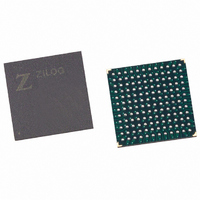
EZ80F91NA050EC Zilog, EZ80F91NA050EC Datasheet - Page 157

EZ80F91NA050EC
Manufacturer Part Number
EZ80F91NA050EC
Description
IC ACCLAIM MCU 256KB 144-BGA
Manufacturer
Zilog
Series
eZ80® Acclaim!®r
Specifications of EZ80F91NA050EC
Core Processor
Z8
Core Size
8-Bit
Speed
50MHz
Connectivity
Ethernet, I²C, IrDA, SPI, UART/USART
Peripherals
Brown-out Detect/Reset, POR, PWM, WDT
Number Of I /o
32
Program Memory Size
256KB (256K x 8)
Program Memory Type
FLASH
Ram Size
16K x 8
Voltage - Supply (vcc/vdd)
3 V ~ 3.6 V
Oscillator Type
Internal
Operating Temperature
-40°C ~ 105°C
Package / Case
144-LBGA
Data Bus Width
8 bit
Maximum Clock Frequency
50 MHz
Number Of Programmable I/os
32
Number Of Timers
16 bit
Operating Supply Voltage
3 V to 3.6 V
Maximum Operating Temperature
+ 105 C
Mounting Style
SMD/SMT
Minimum Operating Temperature
- 40 C
For Use With
269-4712 - KIT DEV ENCORE 32 SERIES269-4671 - BOARD ZDOTS SBC Z80ACCLAIM PLUS269-4561 - KIT DEV FOR EZ80F91 W/C-COMPILER269-4560 - KIT DEV FOR EZ80F91 W/C-COMPILER
Lead Free Status / RoHS Status
Contains lead / RoHS non-compliant
Eeprom Size
-
Data Converters
-
Lead Free Status / Rohs Status
No
Other names
269-3250
Available stocks
Company
Part Number
Manufacturer
Quantity
Price
- Current page: 157 of 384
- Download datasheet (3Mb)
PS019215-0910
Note:
PWM Master Mode
Modification of Edge Transition Values
Table 71. Example: Multi-PWM Addressing
In PWM Master mode, the pair of output signals generated from the PWM0 generator
(PWM0 and PWM0) are directed to all four sets of PWM output pairs. Setting
TMR3_PWM_CTL1[MM_EN] to 1 enables PWM Master mode. Assuming the outputs
are all enabled and no AND/OR gating is used, all four PWM output pairs transition
simultaneously under the direction of PWM0 and PWM0. In PWM Master mode,
the outputs still be gated individually using the AND/OR gating functions described in the
next section. Multi-PWM mode and the individual PWM outputs must be enabled along
with PWM Master mode. It is possible to enable or disable any combination of the four
PWM outputs while running in PWM Master mode.
Special circuitry is included for the update of the PWM edge transition values. Normal use
requires that these values be updated while the PWM generator is running.
Under certain circumstances, electric motors driven by the PWM logic encounters rough
operation. In other words, cycles are skipped if the PWM waveform edge is not carefully
modified.
Without special consideration, if a PWM generator looks for a particular count to make a
state transition and if the edge transition value changes to a value that already occurred in
Parameter
Timer Reload Value
PWM0 rising edge
PWM0 falling edge
PWM1 rising edge
PWM1 falling edge
PWM enable
PWM0 enable
PWM1 enable
Multi-PWM enable
Prescaler Divider = 4
PWM nonoverlapping delay = 0 TMR3_PWM_CTL2[PWM_DLY]
Control Register(s)
{TMR3_RR_H, TMR3_RR_L}
{TMR3_PWM0R_H,
TMR3_PWM0R_L}
{TMR3_PWM0F_H, TMR3_PWM0F_L} 0004h
{TMR3_PWM1R_H,
TMR3_PWM1R_L}
{TMR3_PWM1F_H, TMR3_PWM1F_L} 0007h
TMR3_PWM_CTL1[PAIR_EN]
TMR3_PWM_CTL1[PWM0_EN]
TMR3_PWM_CTL1[PWM1_EN]
TMR3_PWM_CTL1[MPWM_EN]
TMR3_CTL[CLK_DIV]
Programmable Reload Timers
Product Specification
eZ80F91 MCU
Value
000Ch
0008h
0006h
1
1
1
1
00b
0000b
148
Related parts for EZ80F91NA050EC
Image
Part Number
Description
Manufacturer
Datasheet
Request
R

Part Number:
Description:
Communication Controllers, ZILOG INTELLIGENT PERIPHERAL CONTROLLER (ZIP)
Manufacturer:
Zilog, Inc.
Datasheet:

Part Number:
Description:
KIT DEV FOR Z8 ENCORE 16K TO 64K
Manufacturer:
Zilog
Datasheet:

Part Number:
Description:
KIT DEV Z8 ENCORE XP 28-PIN
Manufacturer:
Zilog
Datasheet:

Part Number:
Description:
DEV KIT FOR Z8 ENCORE 8K/4K
Manufacturer:
Zilog
Datasheet:

Part Number:
Description:
KIT DEV Z8 ENCORE XP 28-PIN
Manufacturer:
Zilog
Datasheet:

Part Number:
Description:
DEV KIT FOR Z8 ENCORE 4K TO 8K
Manufacturer:
Zilog
Datasheet:

Part Number:
Description:
CMOS Z8 microcontroller. ROM 16 Kbytes, RAM 256 bytes, speed 16 MHz, 32 lines I/O, 3.0V to 5.5V
Manufacturer:
Zilog, Inc.
Datasheet:

Part Number:
Description:
Low-cost microcontroller. 512 bytes ROM, 61 bytes RAM, 8 MHz
Manufacturer:
Zilog, Inc.
Datasheet:

Part Number:
Description:
Z8 4K OTP Microcontroller
Manufacturer:
Zilog, Inc.
Datasheet:

Part Number:
Description:
CMOS SUPER8 ROMLESS MCU
Manufacturer:
Zilog, Inc.
Datasheet:

Part Number:
Description:
SL1866 CMOSZ8 OTP Microcontroller
Manufacturer:
Zilog, Inc.
Datasheet:

Part Number:
Description:
SL1866 CMOSZ8 OTP Microcontroller
Manufacturer:
Zilog, Inc.
Datasheet:

Part Number:
Description:
OTP (KB) = 1, RAM = 125, Speed = 12, I/O = 14, 8-bit Timers = 2, Comm Interfaces Other Features = Por, LV Protect, Voltage = 4.5-5.5V
Manufacturer:
Zilog, Inc.
Datasheet:

Part Number:
Description:
Manufacturer:
Zilog, Inc.
Datasheet:


