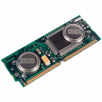
DS2252T-64-16# Maxim Integrated Products, DS2252T-64-16# Datasheet - Page 4

DS2252T-64-16#
Manufacturer Part Number
DS2252T-64-16#
Description
IC MCU 64KB 16MHZ 40-SIMM
Manufacturer
Maxim Integrated Products
Series
DS225xr
Datasheet
1.DS2252T-64-16.pdf
(16 pages)
Specifications of DS2252T-64-16#
Core Processor
8051
Core Size
8-Bit
Speed
16MHz
Connectivity
SIO, UART/USART
Peripherals
Power-Fail Reset, WDT
Number Of I /o
32
Program Memory Type
SRAM
Ram Size
64K x 8
Voltage - Supply (vcc/vdd)
4.5 V ~ 5.5 V
Oscillator Type
External
Operating Temperature
0°C ~ 70°C
Package / Case
40-SIMM
Processor Series
DS2252T
Core
8051
Data Bus Width
8 bit
Program Memory Size
64 KB
Data Ram Size
64 KB
Interface Type
UART
Maximum Clock Frequency
16 MHz
Number Of Programmable I/os
32
Number Of Timers
2
Operating Supply Voltage
4.75 V to 5.25 V
Maximum Operating Temperature
+ 70 C
Mounting Style
SMD/SMT
Minimum Operating Temperature
0 C
Lead Free Status / RoHS Status
Lead free / RoHS Compliant
Eeprom Size
-
Program Memory Size
-
Data Converters
-
Lead Free Status / Rohs Status
Details
Available stocks
Company
Part Number
Manufacturer
Quantity
Price
PIN ASSIGNMENT
PIN DESCRIPTION
PIN
1, 3, 5, 7, 9,
10
4, 6, 8, 10,
12, 14, 16,
40, 38, 36,
34, 32, 30,
1
2
3
4
5
6
7
8
9
11, 13, 15
28, 26
PIN
18
19
21
23
25
27
29
31
33
NAME
P1.0
P1.1
P0.0
P1.2
P0.1
P1.3
P0.2
P1.4
P0.3
V
CC
P0.0 - P0.7. General purpose I/O Port 0. This port is open-drain and cannot drive a
logic 1. It requires external pullups. Port 0 is also the multiplexed Expanded
Address/Data bus. When used in this mode, it does not require pullups.
P1.0 - P1.7. General purpose I/O Port 1.
P2.0 - P2.7. General purpose I/O Port 2. Also serves as the MSB of the Expanded
Address bus.
P3.0 RXD. General purpose I/O port pin 3.0. Also serves as the receive signal for the
on board UART. This pin should NOT be connected directly to a PC COM port.
P3.1 TXD. General purpose I/O port pin 3.1. Also serves as the transmit signal for the
on board UART. This pin should NOT be connected directly to a PC COM port.
P3.2
Interrupt 0. This pin is also connected to the
Clock.
P3.3
Interrupt 1.
P3.4 T0. General purpose I/O port pin 3.4. Also serves as the Timer 0 input.
P3.5 T1. General purpose I/O port pin 3.5. Also serves as the Timer 1 input.
P3.6
bus operation.
P3.7
bus operation.
INT0
INT1
WR
RD
. General purpose I/O port pin. Also serves as the read strobe for Expanded
PIN
. General purpose I/O port pin. Also serves as the write strobe for Expanded
. General purpose I/O port pin 3.3. Also serves as the active low External
11
12
13
14
15
16
17
18
19
20
. General purpose I/O port pin 3.2. Also serves as the active low External
P3.0/RXD
NAME
P1.5
P0.4
P1.6
P0.5
P1.7
P0.6
RST
P0.7
SDI
4 of 16
DESCRIPTION
PIN
22
26
28
29
21
23
24
25
27
30
INTP
P3.1/TXD
P3.2/
P3.3/
P3.4/T0
P3.5/T1
NAME
PROG
ALE
P2.7
P2.6
P2.5
output of the DS1283 Real Time
INT0
INT1
PIN
31
32
33
34
35
36
37
38
39
40
P3.6/
P3.7/
XTAL2
XTAL1
NAME
GND
P2.4
P2.3
P2.2
P2.1
P2.0
WR
RD


